Download

1 / 51
510 likes | 675 Views
Addressing. Outline. Network addressing Network packet format and forwarding NAT, DHCP, IPv6. IP address: 32-bit identifier for host, router interface interface: connection between host/router and physical link router’s typically have multiple interfaces host may have multiple interfaces

E N D
Outline • Network addressing • Network packet format and forwarding • NAT, DHCP, IPv6
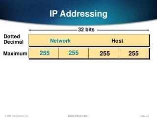
IP address: 32-bit identifier for host, router interface interface: connection between host/router and physical link router’s typically have multiple interfaces host may have multiple interfaces IP addresses associated with each interface 223.1.1.2 223.1.2.1 223.1.3.27 223.1.3.1 223.1.3.2 223.1.2.2 IP Addressing: introduction 223.1.1.1 223.1.2.9 223.1.1.4 223.1.1.3 223.1.1.1 = 11011111 00000001 00000001 00000001 223 1 1 1
IP address: network part (high order bits) host part (low order bits) What’s a network ? (from IP address perspective) device interfaces with same network part of IP address can physically reach each other without intervening router IP Addressing 223.1.1.1 223.1.2.1 223.1.1.2 223.1.2.9 223.1.1.4 223.1.2.2 223.1.1.3 223.1.3.27 LAN 223.1.3.2 223.1.3.1 network consisting of 3 IP networks (for IP addresses starting with 223, first 24 bits are network address)
How to find the networks? Detach each interface from router, host create “islands of isolated networks IP Addressing 223.1.1.2 223.1.1.1 223.1.1.4 223.1.1.3 223.1.7.0 223.1.9.2 223.1.9.1 223.1.7.1 223.1.8.1 223.1.8.0 How many isolated networks? 223.1.2.6 223.1.3.27 Interconnected system consisting of six networks 223.1.2.1 223.1.2.2 223.1.3.1 223.1.3.2
IP address classes 8 16 24 32 Class A Network ID 0 Host ID 1.0.0.0 to 127.255.255.255 Class B 10 Host ID Network ID 128.0.0.0 to 191.255.255.255 Class C Host ID 110 Network ID 192.0.0.0 to 223.255.255.255 Class D 1110 Multicast Addresses 224.0.0.0 to 239.255.255.255 Class E Reserved for experiments 1111
Special IP Addresses • 127.*.*.*: local host (a.k.a. the loopback address) • Private addresses • http://www.rfc-editor.org/rfc/rfc1918.txt • Class A: 10.0.0.0 - 10.255.255.255 (10/8 prefix) • Class B: 172.16.0.0 - 172.31.255.255 (172.16/12 prefix) • Class C: 192.168.0.0 - 192.168.255.255 (192.168/16 prefix) • 255.255.255.255 • IP broadcast to local hardware that must not be forwarded • http://www.rfc-editor.org/rfc/rfc919.txt • Same as network broadcast if no subnetting • IP of network broadcast=NetworkID+(all 1’s for HostID) • 0.0.0.0 • IP address of unassigned host (BOOTP, ARP, DHCP) • Default route advertisement
IP Addressing Problem #1 (1984) • Subnet addressing • http://www.rfc-editor.org/rfc/rfc917.txt • Address problem of inefficient use of address space • For class B & C networks • Class A (rarely given out, not many of them given out by IANA) • Class B = 64k hosts • Very few LANs have close to 64K hosts • Electrical/LAN limitations, performance or administrative reasons • e.g., class B net allocated enough addresses for 64K hosts, even if only 2K hosts in that network • Class C = 256 hosts • Need simple way to get multiple “networks” • Use bridging, multiple IP networks or split up single network address ranges (subnet) • Reduce the total number of addresses that are assigned, but not used
Subnetting • Variable length subnet masks • Subnet a class B address space into several chunks Network Host Network Subnet Host 1111.. ..1111 00000000 Mask
Subnetting Example • Assume an organization was assigned address 150.100 • Assume < 100 hosts per subnet • How many host bits do we need? • Seven • What is the network mask? • 11111111 11111111 11111111 10000000 • 255.255.255.128
IP Address Problem #2 (1991) • Address space depletion • In danger of running out of classes A and B • Class A • Very few in number • IANA frugal in giving them out • Class B • Subnetting only applied to new allocations • sparsely populated • people refuse to give it back • Class C too small for most domains • APNIC has only class C addresses
Some Solution • Solution • Assign multiple consecutive class C address blocks • Supernetting • http://www.rfc-editor.org/rfc/rfc1338.txt • Later known as Classless Inter-Domain Routing (CIDR) • http://www.rfc-editor.org/rfc/rfc1518.txt • http://www.rfc-editor.org/rfc/rfc1519.txt
host part network part 11001000 0001011100010000 00000000 200.23.16.0/23 IP addressing: CIDR • Classful addressing: • inefficient use of address space, address space exhaustion • e.g., class B net allocated enough addresses for 65K hosts, even if only 2K hosts in that network • CIDR:Classless InterDomain Routing • network portion of address of arbitrary length • address format: a.b.c.d/x, where x is # bits in network portion of address
IP addresses: how to get one? Q: How does host get IP address? • hard-coded by system admin in a file • Windows: control-panel->network->configuration->tcp/ip->properties • UNIX: /etc/rc.config • Linux (Redhat): /etc/sysconfig/network-script/ifcfg-eth • DHCP:Dynamic Host Configuration Protocol: dynamically get address from as server • “plug-and-play” (more shortly)
IP addresses: how to get one? Q: How does network get network part of IP addr? A: gets allocated portion of its provider ISP’s address space ISP's block 11001000 00010111 00010000 00000000 200.23.16.0/20 Organization 0 11001000 00010111 00010000 00000000 200.23.16.0/23 Organization 1 11001000 00010111 00010010 00000000 200.23.18.0/23 Organization 2 11001000 00010111 00010100 00000000 200.23.20.0/23 ... ….. …. …. Organization 7 11001000 00010111 00011110 00000000 200.23.30.0/23
200.23.16.0/23 200.23.18.0/23 200.23.30.0/23 200.23.20.0/23 . . . . . . Hierarchical addressing: route aggregation Hierarchical addressing allows efficient advertisement of routing information: Organization 0 Organization 1 “Send me anything with addresses beginning 200.23.16.0/20” Organization 2 Fly-By-Night-ISP Internet Organization 7 “Send me anything with addresses beginning 199.31.0.0/16” ISPs-R-Us
200.23.16.0/23 200.23.18.0/23 200.23.30.0/23 200.23.20.0/23 . . . . . . Hierarchical addressing: more specific routes ISPs-R-Us has a more specific route to Organization 1 Organization 0 “Send me anything with addresses beginning 200.23.16.0/20” Organization 2 Fly-By-Night-ISP Internet Organization 7 “Send me anything with addresses beginning 199.31.0.0/16 or 200.23.18.0/23” ISPs-R-Us Organization 1
Where to obtain IP address Q: How does an ISP get block of addresses? A: ICANN: Internet Corporation for Assigned Names and Numbers • allocates addresses • manages DNS • assigns domain names, resolves disputes
Outline • Overview of Network Layer • Network addressing • Network packet format and forwarding • NAT, DHCP, IPv6
IP datagram: A E B source IP addr misc fields dest IP addr data 223.1.1.1 223.1.2.1 223.1.1.2 223.1.2.9 223.1.1.4 223.1.2.2 223.1.1.3 223.1.3.27 Dest. Net. next router Nhops 223.1.1 1 223.1.3.2 223.1.3.1 223.1.2 223.1.1.4 2 223.1.3 223.1.1.4 2 Getting a datagram from source to dest. forwarding table in A • datagram remains unchanged, as it travels source to destination • addr fields of interest here
B E A 223.1.1.1 223.1.2.1 223.1.1.2 223.1.2.9 223.1.1.4 223.1.2.2 223.1.1.3 223.1.3.27 Dest. Net. next router Nhops 223.1.1 1 223.1.3.2 223.1.3.1 223.1.2 223.1.1.4 2 223.1.3 223.1.1.4 2 Getting a datagram from source to dest. forwarding table in A misc fields data 223.1.1.1 223.1.1.3 Starting at A, send IP datagram addressed to B: • look up net. address of B in forwarding table • find B is on same net. as A • link layer will send datagram directly to B inside link-layer frame • B and A are directly connected
E A B 223.1.1.1 223.1.2.1 223.1.1.2 223.1.2.9 223.1.1.4 223.1.2.2 223.1.1.3 223.1.3.27 Dest. Net. next router Nhops 223.1.1 1 223.1.3.2 223.1.3.1 223.1.2 223.1.1.4 2 223.1.3 223.1.1.4 2 Getting a datagram from source to dest. forwarding table in A misc fields data 223.1.1.1 223.1.2.3 Starting at A, dest. E: • look up network address of E in forwarding table • E on different network • A, E not directly attached • routing table: next hop router to E is 223.1.1.4 • link layer sends datagram to router 223.1.1.4 inside link-layer frame • datagram arrives at 223.1.1.4 • continued…..
Dest. Net router Nhops interface B A E 223.1.1 - 1 223.1.1.4 223.1.2 - 1 223.1.2.9 223.1.3 - 1 223.1.3.27 223.1.1.1 223.1.2.1 223.1.1.2 223.1.2.9 223.1.1.4 223.1.2.2 223.1.1.3 223.1.3.27 223.1.3.2 223.1.3.1 Getting a datagram from source to dest. forwarding table in router misc fields data 223.1.1.1 223.1.2.3 Arriving at 223.1.4, destined for 223.1.2.2 • look up network address of E in router’s forwarding table • E on same network as router’s interface 223.1.2.9 • router, E directly attached • link layer sends datagram to 223.1.2.2 inside link-layer frame via interface 223.1.2.9 • datagram arrives at 223.1.2.2!!! (hooray!)
IP protocol version number 32 bits total datagram length (bytes) header length (bytes) type of service head. len ver length for fragmentation/ reassembly fragment offset “type” of data flgs 16-bit identifier max number remaining hops (decremented at each router) upper layer time to live header checksum 32 bit source IP address 32 bit destination IP address upper layer protocol to deliver payload to E.g. timestamp, record route taken, specify list of routers to visit. Options (if any) data (variable length, typically a TCP or UDP segment) IP datagram format how much overhead with TCP? • 20 bytes of TCP • 20 bytes of IP • = 40 bytes + app layer overhead
network links have MTU (max.transfer size) - largest possible link-level frame. different link types, different MTUs large IP datagram divided (“fragmented”) within net one datagram becomes several datagrams “reassembled” only at final destination IP header bits used to identify, order related fragments IP Fragmentation & Reassembly fragmentation: in: one large datagram out: 3 smaller datagrams reassembly
length =1500 length =1500 length =4000 length =1040 ID =x ID =x ID =x ID =x fragflag =0 fragflag =1 fragflag =0 fragflag =1 offset =0 offset =0 offset =1480 offset =2960 One large datagram becomes several smaller datagrams IP Fragmentation and Reassembly Example • 4000 byte datagram • MTU = 1500 bytes
Fragmentation is Harmful • Uses resources poorly • Forwarding costs per packet • Best if we can send large chunks of data • Worst case: packet just bigger than MTU • Poor end-to-end performance • Loss of a fragment • Reassembly is hard • Buffering constraints
Avoid fragmentation • Path MTU Discovery in IP • http://www.rfc-editor.org/rfc/rfc1191.txt • Hosts dynamically discover minimum MTU of path • Algorithm: • Initialize MTU to MTU for first hop • Send datagrams with Don’t Fragment bit set • If ICMP “pkt too big” msg, decrease MTU • What happens if path changes? • Periodically (>5mins, or >1min after previous increase), increase MTU • Some routers will return proper MTU • MTU values cached in routing table
used by hosts, routers, gateways to communication network-level information error reporting: unreachable host, network, port, protocol echo request/reply (used by ping) network-layer “above” IP: ICMP msgs carried in IP datagrams ICMP message: type, code plus first 8 bytes of IP datagram causing error ICMP: Internet Control Message Protocol TypeCodedescription 0 0 echo reply (ping) 3 0 dest. network unreachable 3 1 dest host unreachable 3 2 dest protocol unreachable 3 3 dest port unreachable 3 6 dest network unknown 3 7 dest host unknown 4 0 source quench (congestion control - not used) 8 0 echo request (ping) 9 0 route advertisement 10 0 router discovery 11 0 TTL expired 12 0 bad IP header
Traceroute • Based on ICMP: provides delay measurement from source to router along end-end Internet path towards destination. • sends three packets that will reach router i on path towards destination • Set the TTL incrementally from 1 up to 30 • router i will return ICMP warning (type 11) back. • sender times interval between transmission and reply. TTL=3 TTL=1 TTL=2
Outline • Network addressing • Network packet format and forwarding • NAT, DHCP, IPv6
NAT: Network Address Translation rest of Internet local network (e.g., home network) 10.0.0/24 10.0.0.1 10.0.0.4 10.0.0.2 138.76.29.7 10.0.0.3 Datagrams with source or destination in this network have 10.0.0/24 address for source, destination (as usual) All datagrams leaving local network have same single source NAT IP address: 138.76.29.7, different source port numbers
NAT: Network Address Translation • Motivation: local network uses just one IP address as far as outside word is concerned: • no need to be allocated range of addresses from ISP: - just one IP address is used for all devices • can change addresses of devices in local network without notifying outside world • can change ISP without changing addresses of devices in local network • devices inside local net not explicitly addressable, visible by outside world (a security plus).
NAT: Network Address Translation Implementation A NAT router must: • outgoing datagrams:replace (source IP address, port #) of every outgoing datagram to (NAT IP address, new port #) . . . remote clients/servers will respond using (NAT IP address, new port #) as destination addr. • remember (in NAT translation table) every (source IP address, port #) to (NAT IP address, new port #) translation pair • incoming datagrams:replace (NAT IP address, new port #) in dest fields of every incoming datagram with corresponding (source IP address, port #) stored in NAT table
3 1 2 4 S: 10.0.0.1, 3345 D: 128.119.40.186, 80 S: 138.76.29.7, 5001 D: 128.119.40.186, 80 1: host 10.0.0.1 sends datagram to 128.119.40, 80 2: NAT router changes datagram source addr from 10.0.0.1, 3345 to 138.76.29.7, 5001, updates table S: 128.119.40.186, 80 D: 10.0.0.1, 3345 S: 128.119.40.186, 80 D: 138.76.29.7, 5001 NAT: Network Address Translation NAT translation table WAN side addr LAN side addr 138.76.29.7, 5001 10.0.0.1, 3345 …… …… 10.0.0.1 10.0.0.4 10.0.0.2 138.76.29.7 10.0.0.3 4: NAT router changes datagram dest addr from 138.76.29.7, 5001 to 10.0.0.1, 3345 3: Reply arrives dest. address: 138.76.29.7, 5001
DHCP: Dynamic Host Configuration Protocol Goal: allow host to dynamically obtain its IP address from network server when it joins network Can renew its lease on address in use Allows reuse of addresses (only hold address while connected an “on” Support for mobile users who want to join network (more shortly) DHCP overview: • host broadcasts “DHCP discover” msg • DHCP server responds with “DHCP offer” msg • host requests IP address: “DHCP request” msg • DHCP server sends address: “DHCP ack” msg
E B A DHCP client-server scenario 223.1.2.1 DHCP 223.1.1.1 server 223.1.1.2 223.1.2.9 223.1.1.4 223.1.2.2 arriving DHCP client needs address in this network 223.1.1.3 223.1.3.27 223.1.3.2 223.1.3.1
DHCP discover src : 0.0.0.0, 68 dest.: 255.255.255.255,67 yiaddr: 0.0.0.0 transaction ID: 654 DHCP client-server scenario arriving client DHCP server: 223.1.2.5 DHCP offer src: 223.1.2.5, 67 dest: 255.255.255.255, 68 yiaddrr: 223.1.2.4 transaction ID: 654 Lifetime: 3600 secs DHCP request src: 0.0.0.0, 68 dest:: 255.255.255.255, 67 yiaddrr: 223.1.2.4 transaction ID: 655 Lifetime: 3600 secs time DHCP ACK src: 223.1.2.5, 67 dest: 255.255.255.255, 68 yiaddrr: 223.1.2.4 transaction ID: 655 Lifetime: 3600 secs
IPv6 • Initial motivation:32-bit address space completely allocated by 2008. • Additional motivation: • header format helps speed processing/forwarding • header changes to facilitate QoS • new “anycast” address: route to “best” of several replicated servers • IPv6 datagram format: • fixed-length 40 byte header • no fragmentation allowed
IPv6 Header (Cont) Priority: identify priority among datagrams in flow Flow Label: identify datagrams in same “flow.” (concept of“flow” not well defined). Next header: identify upper layer protocol for data
IPv4 vs. IPv6 type of service head. len ver total length fragment offset flgs 16-bit identifier time to live Internet checksum protocol 32 bit source IP address 32 bit destination IP address Options (if any) data (variable length, typically a TCP or UDP segment)
Differences Between Ipv4 and IPv6 • Address length: 32 vs. 128 • Fragmentation: IPv6 has no fragmentation • Type of service (TOS): IPv6 has no TOS • Checksum:removed entirely to reduce processing time at each hop • Options: allowed, but outside of header, indicated by “Next Header” field; options specify how to deal with the packet if a header is unknown • ICMPv6: new version of ICMP • additional message types, e.g. “Packet Too Big” • multicast group management functions
Transition From IPv4 To IPv6 • Not all routers can be upgraded simultaneous • no “flag days” • How will the network operate with mixed IPv4 and IPv6 routers? • Two proposed approaches: • Dual Stack: some routers with dual stack (v6, v4) can “translate” between formats • Tunneling: IPv6 carried as payload in IPv4 datagram among IPv4 routers
Flow: ?? Src: A Dest: F data Flow: X Src: A Dest: F data D A B E F C Src:A Dest: F data Src:A Dest: F data Dual Stack Approach IPv6 IPv6 IPv6 IPv6 IPv4 IPv4 A-to-B: IPv6 B-to-C: IPv4 B-to-C: IPv6 B-to-C: IPv4
Flow: X Src: A Dest: F data Flow: X Src: A Dest: F data Flow: X Src: A Dest: F data Flow: X Src: A Dest: F data D C F E B A F E B A Src:B Dest: E Src:B Dest: E Tunneling tunnel Logical view: IPv6 IPv6 IPv6 IPv6 Physical view: IPv6 IPv6 IPv6 IPv6 IPv4 IPv4 A-to-B: IPv6 E-to-F: IPv6 B-to-C: IPv6 inside IPv4 B-to-C: IPv6 inside IPv4
IP quality of service • IP originally had “type-of-service” (TOS) field to eventually support quality • Not used, ignored by most routers • Then came int-serv (integrated services) and RSVP signalling • Per-flow quality of service through end-to-end support • Setup and match flows on connection ID • Per-flow signaling • Per-flow network resource allocation (*FQ, *RR scheduling algorithms)
IP quality of service • RSVP • http://www.rfc-editor.org/rfc/rfc2205.txt • Provides end-to-end signaling to network elements • General purpose protocol for signaling information • Not used now on a per-flow basis to support int-serv, but being reused for diff-serv. • int-serv • Defines service model (guaranteed, controlled-load) • Dozens of scheduling algorithms to support these services • WFQ, W2FQ, STFQ, Virtual Clock, DRR, etc. • If this class was being given 5 years ago….
IP quality of service • Why did RSVP, int-serv fail? • Complexity • Scheduling • Routing • Per-flow signaling overhead • Lack of scalability • Per-flow state • Route pinning • Economics • Providers with no incentive to deploy • SLA, end-to-end billing issues • QoS a weak-link property • Requires every device on an end-to-end basis to support flow
IP quality of service • Now it’s diff-serv… • Use the “type-of-service” bits as a priority marking • Core network relatively stateless • AF • Assured forwarding (drop precedence) • EF • Expedited forwarding (strict priority handling)