Download
1 / 17
170 likes | 171 Views
This talk outlines two concepts for raising acceleration gradients: reducing exposure time with multi-mode cavity excitation and using a longitudinally asymmetric cavity. Experimental tests and complementary experiments are suggested. Principle of acceleration in a multi-frequency structure is explained. Raising RF breakdown thresholds and possible experiments using CTF-3 beam facilities are discussed.

E N D
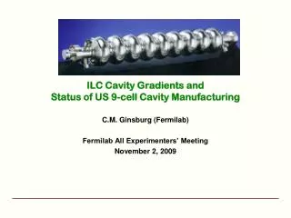
TWO CONCEPTS FOR RAISING ACCELERATION GRADIENTSBY USING MULTI-MODED CAVITYSTRUCTURES# S.V. Kuzikov1,2, S.Yu. Kazakov1,3, J.L. Hirshfield1,4, M.E. Plotkin2, A.A. Vikharev2, V.P. Yakovlev1,5 1Omega-P, Inc., New Haven, CT, USA 2Institute of Applied Physics, Nizhny Novgorod, Russia 3KEK, Tsukuba, Japan 4Yale University, New Haven, CT, USA 5Fermi National Accelerator Laboratory, Batavia, IL, USA # Work sponsored by in part by US Department of Energy, Office of High Energy Physics (2009).
OUTLINE OF TALK • Previously,* we suggested a concept aimed at raising RF breakdown thresholds by reducing the exposure time of surfaces to high E and H fields, through the use of multi-mode cavity excitation. • A second related idea aims at the same objective by using a two-mode, two-frequency axisymmetric, but longitudinally asymmetric cavity. • Experimental tests of both ideas may be possible using CTF-3 beam facilities. • Methodology and possible time-schedule are suggested. • Complementary experiments may also be possible using two klystrons as the RF sources (S-band/C-band or C-band/X-band), rather than a drive beam. • Summary. • *Papers at AAC2006, AAC2008, PAC2009.
Principle of acceleration in a multi-frequency structure A Acceleration is shown of a moving periodic sequence of bunches in decoupled cavities, eachoperating in a superposition of harmonic modes. A E-field in A-A cross-section 1 – ideal (desired) time-dependence of the field. 2 – time-dependence of the field in an ordinary single-frequency structure. 3 – time-dependence of the field in a multi-frequency structure (with finite number of modes).
This solution is periodic in time (period is that of the lowest mode). Therefore, thespectrum of eigenmodes of each cavity has to be equidistant. lb bunches (vc) wheren=0,1,2,… Here0/=p/q, wherep andq are arbitrary integers. When operating with a finite number of modes, the single peak duration is defined by the time during which the phases of the lowest- and highest-frequency modes differ by , i.e.,
There are additional criteria proposed: • Modified Poynting vector (W. Wuensch et al) • Pulse heating and the stored energy (V.Dolgashev et al) Raising breakdown thresholds W. Wuensch et al (2008) suggested to consider the initial stage of RF breakdown, in order to find a criterion governing breakdown ignition. It is postulated that a necessary condition for initiating breakdown is surface heating by emission currents up to a threshold temperature Tthr. This leads to a scaling law connecting the E field magnitude and pulse duration which was confirmed experimentally, namely E(t)andI(t) dependenciesfor single-(1) and multi-frequency (2) structures One may question how this scaling law might be modified if the exposure times to intense RF fields are shortened within each RF cycle, i.e. into the psec range.
Fields versus time for a single-mode 3 GHz cavity, and for 3+6+9 GHz multi-mode cavity. Fields versus time for single 3 GHz cavity, for 15 GHz cavity, and for 3+9+15 GHz multi-mode cavity. In this case one may expect similar raise of breakdown threshold by a factor of ~(2*(9-3)/3)1/6 = 1.26. In this case one may expect a raise in breakdown threshold by a factor ~51/6 = 1.3. However, there is to date no experimental proof that the initiation of breakdown can be inhibited by reducing the micro-pulse width of RF fields, as contrasted with the customary role assumed for the macro-pulse width. An objective of our proposed experiments is to test that postulate.
Possible experiments with cavities powered by CTF3 beam • We propose to build three cavities to be excited identically (by means of the same e-beam). • We would like to compare probabilities of breakdown in these three cases: 1-, 2-, and 3-mode cavities. • The experiment conditions should provide the same E-field level in each cavity, in order to deal only with effect of the different exposure time. • If our postulate is valid, the 3-mode cavity will be the most breakdown proof among the three. CTF3 beam • These experiments are aimed at investigating the fundamental basis of RF breakdown theory. • We plan to investigate dependencies of the breakdown threshold on the temporal and spatial cyclic exposures of cavity surfaces to E- and H-fields. • Investigations have already been made by others of breakdown dependencies on the field magnitude and macro-pulse duration, but not the shape of RFpulse. • If a rise of breakdown threshold through reduction in the micro-pulse width can be proven, it could open a new means for accelerating particles with a higher gradient than through use of single-mode excitation.
Three-mode axisymmetric cavity with modes at 3, 6, and 9 GHz The first design issue is to obtain an equidistant mode spectrum. This has been solved by specific cavity shape (each mode is tuned by its own sine-like wall profile. Beam channel E-fields of eigenmodes
CTF3 beam parameters assumed in obtaining numerical results The maximum Poynting vector value in three mode cavity is SC=0.45 W/m2.
2nd concept: Raising breakdown threshold by using an asymmetric cavity b) U U a) Cathode Anode Cathode Anode It is known for DC vacuum breakdown that, even when the voltage is the same, in case (a) breakdown threshold is higher than in case (b)! Cathode is more vulnerable. node Instantaneous field G > E_bdn High field “Anode” Low field “cathode” athode Non-symmetric RF cavity With RF fields, electron emission does not occur if the E-field pushes electrons in towards a wall. In a single mode cavity this doesn’t help, since fields oscillate symmetrically between +maximum and –maximum. “Cathode” and “Anode” exchange roles each half period. In a multi-mode cavity, the situation may be quite different!
A multi-mode cavity without longitudinal symmetry allows unequal “anode” and “cathode” fields at metal surfaces, and can have an “anode” field higher than the “cathode” field. If it is correct that breakdown is determined only by the cathode field, it may be that a non-symmetric cavity will have a higher ratio of accelerating gradient to surface breakdown field, and will thus provide an increased acceleration gradient. bunches A C C A A C A C C A In the RF cavity “anode” and “cathode” change places with frequency f.
We consider a cavity having two axisymmetric modes at frequencies f and 2f. “Anode” “Anode” “Cathode” Ez Right wall Left wall E0 E1 0 L Longitudinal field distribution of the first asymmetric mode at frequency f Ez Field on the left wall The field on the left wall has maximum about +2E0. But +2E0 is actually “anode” field. “Cathode” field on the left wall is -E0. The field on the right wall has maximum E1+E2 <E0 (assumed to be less than breakdown threshold) due to asymmetry. E0 E2 0 L Longitudinal field distribution of the second asymmetric mode at frequency 2f
Optimal combination (amplitudes): Af = 1, A2f = 0.65 a2 = G / E_cth = 1.25 Improvement in this ratio is a2 / af = 1.25 / 0.93 = 1.33, suggesting a 33% increase in gradient without an increase in the “cathode” field, by use of a two-mode cavity.
If this concept can be proven, a future accelerating structure could have the following shape: Conclusion: By adding a relatively small amplitude (0.35-0.5) of second harmonic, it may be possible to increase accelerating gradient by aboutone-third without an increase in breakdown probability.
Use of two klystrons to power two-mode cavity, instead of drive beam An alternative experiment scheme is to power a multi-mode cavity using independent coherent RF sources. This scheme provides greater flexibility then does use of a drive beam, since one would be able to vary powers and phases, and to compare single-mode regime with multi-mode regime in the same cavity. . A key question is how to provide effective isolation between klystrons. f1= 3 GHz,Q0=7×10³, f2 = 6 GHz, Q0=11×103. Two-mode cavity 6 GHz radiation 3 GHz radiation Two-mode cavity Selective 6 GHz reflector
No hole F2=6 GHz, Qdiffr=7.8×10⁵ RF F2=6 GHz, QloadQ0 RF F1=3 GHz, Qload=6.2×10³ QloadQ0
Summary • We propose experiments with multi-mode cavities aimed at raising • the RF breakdown threshold, as a step towards understanding the • fundamental nature of RF breakdown. • 2. Two kinds of test cavities have been discussed, namely • - axisymmetric cavities powered by a drive beam like CTF3, and • - axisymmetric cavity having longitudinally asymmetric modes, • powered either by a drive beam, or by independent RF sources. • Methodology involves comparison of breakdown probabilities in 1-, 2-, and 3-mode cavities having the same E-field levels, and visual observation of breakdown within the cavities. • Start of experiments could be towards the end of 2010 to the • beginning of 2011.