Download
1 / 5
0 likes | 2 Views
Discover the ultimate solution for your agricultural water needs with Trubore Pipes' Borewell Piping System. Engineered for efficiency and durability, our comprehensive range of piping systems ensures reliable water supply for irrigation. <br><br>From robust materials to precision engineering, Trubore Pipes delivers unmatched performance, maximizing crop yields and minimizing water wastage. <br><br>Trust Trubore Pipes for superior quality and innovation in agricultural water management. Explore our Borewell Piping System today and experience the difference.

E N D
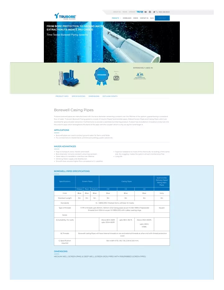
1800 266 8222 ABOUT US NEWS SITEMAP PRODUCTS DOWNLOADS VIDEOS CONTACT US BLOG NEED HELP? FROM BORE PROTECTION TO GROUND WATER EXTRACTION,ITS INDIA’S TRU CHOICE Time-Tested Borewell Piping systems EXTENSIVELY USED IN Pipes as per IS:12818 AGRICULTURE PRODUCT INFO SPECIFICATIONS DIMENSIONS DO’S AND DONT’S Borewell Casing Pipes Trubore borewell pipes are manufactured with the bore diameter remaining constant over the lifetime of the system, guaranteeing a consistent ?ow of water. Trubore’s Borewell Piping systems consist of Column Pipes/ Submersible pipes, Ribbed Screen Pipes and Casing Pipes which are essential for groundwater extraction. Furthermore, to provide a seamless functioning product, Trubore has included an innovative circlip lock into the column pipe which strengthens the bond of the pipe with the coupler which is why we say ?t it and forget it. APPLICATIONS Borewell pipes are used to extract ground water for farms and ?elds. For connections to residential & commercial buildings, public places etc. MAJOR ADVANTAGES Easy to transport, store, handle and install. Bore diameter remains constant, ensuring constant. Saves labour & installation cost.?ow over lifetime Drinking Water supply and distribution. Smooth bore ensures higher ?ow compared to G.I. pipeline. Superior resistance to most of the chemicals, no scaling, of the same size. No clogging. makes the system almost maintenance free. Long life. BOREWELL PIPES SPECIFICATIONS Submersilbe Delivery Pipes/ Rising Main Pipes Speci?cations Screen Pipes Casing Pipes protected by reCAPTCHA - Privacy - Terms Ribbed Plain Medium CM CS CD Color Blue Blue Blue Blue Blue Blue Ivory Standard Length 3m 3m 3m 3m 3m 3m 3m Standards IS – 12818-2010 / Marked items will bear ISI marks Type of threads 11 TPI V threads upto 80mm, 100mm (CS) Casing pipes as per IS-554-1999 & Trapezoidal threads form 100mm as per IS-12818-2010 with rubber sealing rings. Square Notes: A) Suitability: For wells Above 80m 262ft upto 250m 820ft upto 80m 262 ft. Above 250m 820ft. upto 450m 1476ft. B) Threads Borewell casing Pipes will have internal threads at one end external threads at other end with thread protection cover. C) Speci?cation required Slot width 0.75, 1.00, 1.50, 2.00 & 3.00 mm. DIMENSIONS MEDIUM WELL SCREEN (RMS) & DEEP WELL SCREEN (RDS) PIPES WITH RIBS/RIBBED SCREEN PIPES.
Medium Well Screen(RMS) Deep Well Screen(RDS) Wall Nominal Diameter (DN) Mean Outer Diameter of pipe (d) (mm) Mean Outer Diameter over Connection, (d’s’) Mean Outer Diameter over Connection, (d’s’) Wall Thickness ‘e’ (under ribs) (mm) Thickness, ’e’ (mm) Inches mm Min Max Max Min Max Max Min Max 1 1/2 40.0 52.00 52.20 56.00 3.50 4.00 – – – 2 50.0 64.00 64.20 69.00 4.00 4.60 – – – 3 80.0 92.00 92.30 98.00 4.00 4.60 – – – 4 100.0 117.00 117.30 124.00 5.00 5.70 129.00 7.00 7.90 4 1/2 115.0 129.00 129.30 – – – 141.00 7.50 8.50 5 125.0 144.00 144.40 154.00 6.50 7.30 156.00 8.00 9.00 6 150.0 169.00 169.40 182.00 7.50 8.50 184.00 9.50 10.70 7 175.0 204.00 204.50 219.00 8.80 9.80 221.00 11.80 13.60 8 200.0 229.00 229.50 247.00 10.00 11.20 251.00 13.00 14.80 10 250.0 284.00 284.50 302.00 12.50 14.00 309.00 16.00 17.60 12 300.0 334.00 334.60 356.00 14.50 16.20 363.00 19.00 21.00 14 350.0 404.00 404.70 432.00 17.50 19.50 437.00 21.50 23.90 16 400.0 454.00 454.80 483.00 19.50 21.70 494.00 23.50 26.10 PLAIN WELL SCREEN (PMS) & PLAIN DEEP WELL SCREEN (PDS) PIPES Plain Medium Well Screen(PMS) Plain Deep Well Screen(PDS) Mean Outer Diameter over Connectio n, (d’s’) Mean Outer Diameter over Connection, (d’s’) Mean Outer Diameter of pipe (d) (mm) Outer Nominal Diameter (DN) Wall Wall Diameter at any point d’e’ (mm) Thickness (e) (mm) Thickness, ’e’ (mm) Inche s mm Min Max Max Min Max Min Max Max Min Max 8 200 225.00 225.50 243.00 10.0 0 11.20 224.5 0 225.8 0 247.00 13.0 0 14.8 0 10 250 280.0 0 280.5 0 298.00 12.50 14.0 0 279.4 0 280.8 0 304.00 16.0 0 17.60 12 300 330.0 0 330.6 0 352.00 14.5 0 16.20 329.3 0 331.00 359.00 19.0 0 21.00 14 350 400.0 0 400.7 0 428.00 17.50 19.50 399.2 0 401.20 433.00 21.50 23.9 0 16 40 0 450.0 0 450.8 0 479.00 19.50 21.70 449.1 0 451.30 490.00 23.5 0 26.10 MEDIUM WELL CASING PIPES (CM) & SHALLOW WELL CASING (CS) PIPES. Medium Well Casing (CM) Pipes Shallow Well Casing (CS) Pipes Nominal Diameter (DN) Mean Outer Diameter of pipe (d) (mm) Mean Outer Diameter over Connection, (d’s’) Wall Mean Outer Diameter over Connection, (d’s’) Wall Thickness ‘e’ (mm) Thickness, ’e’ (mm) Inches mm Min Max Max Min Max Max Min Max 1 1/2 40.0 48.00 48.20 52.00 3.50 4.00 – – – 2 50.0 60.00 60.20 65.00 4.00 4.60 – – – 3 80.0 88.00 88.30 94.00 4.00 4.60 – – – 4 100.0 113.00 113.30 120.00 5.00 5.70 – – – 5 125.0 140.00 140.40 150.00 6.50 7.30 – – – 6 150.0 165.00 165.40 178.00 7.50 8.50 174.00 5.70 6.50 7 175.0 200.00 200.50 215.00 8.80 9.80 211.00 7.00 7.80 8 200.0 225.00 225.50 243.00 10.00 11.20 238.00 7.60 8.80 10 250.0 280.00 280.50 298.00 12.50 14.00 292.00 9.60 11.00 12 300.0 330.00 330.60 352.00 14.50 16.20 – – – DEEP WELL CASING PIPES (CD) Nominal Diameter (DN) Mean Outer Diameter of pipe d’em’ (mm) Outer Diameter at any point d’e’ (mm) Mean outer Diameter over Connection, (d’s’) Wall thickness, ‘e’ (mm) Inches mm Min Max Min Max Max Min Max 4 100.0 113.00 113.30 112.80 113.40 125.00 7.00 7.90 4 1/2 115.0 125.00 125.30 124.90 125.40 137.00 7.50 8.50
5 125.0 140.00 140.40 139.70 140.50 152.00 8.00 9.00 6 150.0 165.00 165.40 164.60 165.60 180.00 9.50 10.70 7 175.0 200.00 200.50 199.60 200.60 217.00 11.80 13.60 8 200.0 225.00 225.50 224.50 225.80 247.00 13.00 14.80 10 250.0 280.00 280.50 279.40 280.80 304.00 16.00 17.60 12 300.0 330.00 330.60 329.30 331.00 359.00 19.00 21.00 14 350.0 400.00 400.70 399.20 401.20 433.00 21.50 23.90 16 400.0 450.00 450.80 449.10 451.30 490.00 23.50 26.10 SUBMERSIBLE DELIVERY PIPES/RISING MAIN PIPES Ultim ate Breaki ng Load (Kg) Safe Pullin g Load (Kg) Product Press ure Kg/c m² Safe total pump delivery Head(m) STD Pack ing OD-Outside Dia. ND-Nominal Dia. In mm Screen Colour Size Type Category 1″ OD-33.30 ND-25.00 Coupler V 4 12.5 125 850 500 Royal Claret 28 17 170 950 600 Green Mediu m 22 220 1250 750 Orange 28 Std 38 380 1750 1100 Red 28 Bell Form Coupler V 4 12.5 125 850 500 Royal Claret 28 17 170 950 600 Green 1 1/4″ OD-42.10 ND- 32.00 Coupler V 4 12.5 125 1350 800 Royal Claret 20 17 170 1500 900 Green Mediu m 21 210 1725 1000 Orange 20 Std 30 300 2350 1400 Red 20 Heavy 39 390 2900 1750 Blue 20 Bell Form Coupler V 4 12.5 125 1350 800 Royal Claret 20 17 170 1500 900 Green 1 1/2″ OD-48.20 ND- 40.00 Coupler V 4 16 160 1850 1100 Green 16 Mediu m 22 220 2400 1450 Orange 16 Std 26 260 2750 1650 Red 16 Heavy 39 390 3700 2250 Blue 16 2″ OD-60.20 ND- 50.00 Coupler Mediu m 14 140 2450 1450 Orange 12 Std 20 200 3500 2100 Red 12 Heavy 27 270 4600 2800 Blue 12 2 1/2″ OD-75.00 ND- 65.00 Coupler Mediu m 11 110 3100 1800 Orange 8 Std 16 160 4500 2700 Red 8 Heavy 26 260 6450 3900 Blue 8 3″ OD-88.00 ND- 80.00 Coupler Mediu m 11 110 4100 2450 Orange 6 Std 17 170 6400 3800 Red 6 Heavy 26 260 8900 5300 Blue 6 4″ OD-113.00 ND- 100.00 Coupler Mediu m 10 100 6500 3900 Orange 4 Std 15 150 9250 5550 Red 4 Heavy 26 260 1445 0 8700 Blue 4 DO’S & DONT’S JOINTING & INSTALLATION.
Ensure that pipes threads are proper and clean it with normal water to avoid forceful jointing. Don’t use any chemical for cleaning the pipe thread. Don’t apply lubricant on borewell casing pipe thread. Ensure that rubber seal is properly sealed in its position, without any twist/cut while tightning the threads to avoid leakages. Don’t over-tighten the joints to avoid breakages. Before jointing the pipes with pump, it is recommended to provide pump guard between pipe coupler and pipe metal adapater. Don’t use pipe/chain wrench to tighten the joints. Assemble the TRUBORE G I metal adapter with pump. Don’t dump gravel at a very high rate to avoid excess abrasion. During assembly of the pipe.,initially hold the pipe coupler with hands & tighten it, for ?nal jerk always use rope strap wrench to tighten the pipe properly. Don’t use any chemical for cleaning the pipe thread. Fix a nylon rope to cast iron adapter as a safety measure against failing of submersible pump due to mishape. Don’t use agri-pipes(with solvent cement joint) for borewells, as their mechanical strength is not designed for this application. Clamp the pipe below coupler (at de?ned location at pipe) at the time of lowering Trubore rising main pipe into the borewell. Don’t hammer the pipes during assembly. Always use chain pulley for lowering Trubore rising main pipe. HANDLING, TRANSPORTATION & STORAGE. Pipes shall be stored in shade on resonably ?at surfaces, free from sharp objects. Don’t hammer the pipes during assembly. Don’t dump the pipes over each other. Don’t remove the packing & thread protection covers of borewell pipes till the time of installation. Don’t drag/throw the pipes during handling to avoid thread damages. GUIDELINES FOR INSTALLATION OF SCREEN & CASING PIPE. Drill the bore of the required size & depth in the gorund using the method of auger drilling/water jet boring/hydraulic rotart drilling/core drilling. During drilling, care should be taken that it is vertically straight down without any bends. To contstruct the bore/tube well, CASING/SCREENING & RISING MAIN pipes are required. CASING pipes are highly recommended in the area where loose soil & slit/loose boulders & loose stones are prevalent. Fit the rubber gasket properly on the space provided on the ribbed screen/casing pipes. Fit C damp below the bell end on the pipe and lower the assembly done with the help of chain pulley block (Provide sand trap with endplug as necessary). Ater lowering the pipe up to the clamp level, ?x the rubber gasket on another pipe & tighten it gently with the lowered pipe. After tightening, use pipe/chain wrench for proper jointing, but do not over tighten. Fix the next clamp with the pipe above and bend below and connect the chain pulley with clamp. Remove the clamp of lowered pipe & start lowering further. Repeat the jointing method till the required depth of borewell. Centering guide to be ?tted wherever necessary. Fill the gravel between pipe & bore hole. GUIDELINES FOR INSTALLATION OF RISING MAIN PIPE.
Once screen & casing pipes are installed properly, follow the below guidelines for installation of PUMP & SUBMERSIBLE DELIVERY PIPE. Before starting installation, pre-check if submersible pump is in good working condition. Join the Trubore metal adapter with the submersible pump with the help of chain wrench Before starting the pipe assembly, clean the pipe threads with normal water to avoid forceful jointing. Before joining the pipe with pump, ensure the pump guard is installed properly between pipe coupler & pump metal adapter. Assemble SUBMERSIBLE DELIVERY PIPE with pump, always use strap wrench/rope for last jerk. Fix a nylon rope to cast iron adapter as a safety measure against falling of submersible pump due to mishap (run the nylon rope throughout the borewell length & tie it with top clamp). Fit the C clamp below coupler(at de?ned location on pipe) & lower the assembly inside the CASING pipe carefully with the help of a chain pulley. Once casing pipe will be lowered in the borewell up to the clamp level, ?x the rubber ring on the other pipe & tighten it gently with the help of rope/strap wrench, till half of the ring gets inside the coupler. NEED HELP ? Enquiry Type Enquiry States & U.T. 10 digit Mobile Number Submit © 2020 – 2024 TRUBORE PIPES Designed by Butter?y Themes®.