Download
1 / 40
410 likes | 616 Views
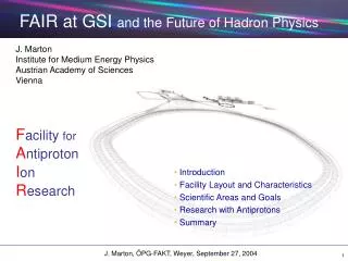
Vacuum and electron cloud issues at the GSI present and future facilities Giovanni Rumolo , O. Boine-Frankenheim, I. Hofmann, E. Mustafin. Overview on the GSI existing machines and the future I nternational A ccelerator P roject

E N D
Vacuum and electron cloud issues at the GSI present and future facilitiesGiovanni Rumolo,O. Boine-Frankenheim, I. Hofmann, E. Mustafin • Overview on the GSI existing machines and the future International Accelerator Project • Vacuum requirements and beam life time due to the dynamic vacuum • Measurements of theion desorption yield • The e-cloud in the SIS18 and SIS100/300: thresholds for build up and instability • Conclusions and outlook
The GSI Accelerator (existing) Facility Ion sources 110 Ds 269 SIS18 Unilac ESR 2004: 1010/s U73+ 1 GeV/u Tumor therapy
Gain compared to the existing facility / • new and special beam properties: • Primary beam intensities: Factor 100 – 1000 • Ion energy: Factor 15 (25) 1.5 GeV/u U28+ 1012 /s 29 GeV p 1013 /s 22 (35) GeV/u U92+ 109 /s Superconducting double-synchrotron SIS 100/300 GSI international accelerator project
Gain compared to the existing facility / • new and special beam propoerties: • Primary beam intensities: Factor 100 – 1000 • Ion energy: Factor 15 (25) • Secondary beam intensities for radioactive Ions: up to a factor 10000 • New: cooled antiproton beams up to • 15 GeV • Special: intense cooled radioactive • ion beams • efficient parallel operation of several experiments 1.5 GeV/u U28+ 1012 /s 29 GeV p 1013 /s 22 (35) GeV/u U92+ 109 /s Superconducting double-synchrotron SIS 100/300 HESR 2004: 1010/s U73+ 1 GeV/u CR NESR GSI international accelerator project
Applications and requirements of the new facility • Nuclear Structure and Astrophysics Primary beam: 1 GeV/u 1012/s Uranium ions Pulse structure on the target: 50 ns single pulse (1 Hz) or ‘dc’ Secondary beams: Stored exotic nuclei 0-900 MeV/u • Research with Antiprotons Primary beam: 30 GeV 4x10¹³/pp Protons Pulse structore on target: 50 ns single pulse (0.2 Hz) Secondary beams: Stored antiprotons 1-15 GeV • Nucleus-Nucleus Collisions at High Energy Primary beam: 20-30 GeV/u 109/s Uranionen Pulse structure on the target: ‘dc’ • Dense Plasma Physics Primary beam: 0.4-1 GeV/u >1012/pp Uranium ions Pulse structure on the target: 50 ns single pulse
Vacuum Requirements for SIS18 Beam lifetime has to be significantly larger than cycling time of the SIS18 (Lifetime of at least 10 seconds for all kinds of operation) Total pressure in the low 10-12 mbar range with a small fraction of high Z gases even for highest beam intensities • optimized dynamic conditions: • efficient ion beam loss control, • low desorption at localized ion beam losses, • maximized local pumping speed at locations of ion beam loss, • No beam scrubbing possible due to multi-user operation of SIS18 • optimized static conditions: • minimized outgassing rate through material and production control, cleaning, bakeout, • removal of contaminations and "micro-leaks" • efficient and distributed pumping.
Dynamic Vacuum and Beam Lifetime P. Spiller, December 2001 8.75 MeV/u U28+ Desorption processes degenerate the residual gas pressure. • Systematic beam losses on acceptance limiting devices (e.g. septa) Energies from 8 to 100 MeV/u and incidence at random angles • Stripped beam ions Energies from 8 to 100 MeV/u and incidence at shallow angles • Ionized and accelerated residual gas Energies in the keV range and normal incidence Beam losses increase with number of injected ions (shorter beam life time due to pressure instability)
Desorption Processes in SIS18 vacuum chamber wall S: pumping speed/therm. desorption X septum or collimator X hloss X X UZ+ UZ+ UZ+ q e sX sloss X X X X Xq+ UZ+q hX hloss beam loss induced desorption ion induced desorption desorption yield h:
Beam Loss Distribution in the synchrotrons U28+ beam Dipole magnet capture stripping U28+/U29+ beam U29+ corresponds to a momentum offset of dp/p=-3.5 % P. Spiller (2003)
U28+ Lifetime and UHV Requirementsin the Synchrotrons U28+ operation with 1 % stripping loss means: 10 s lifetime in SIS (4 Hz) or P=5x10-11 mbar 100 s lifetime in SIS 100/300 (T= 1 s) or P=5x10-12 mbar Scaling of the stripping cross section: Projectile-Stripping in the residual gas: U28+ Beam lifetime measurements in SIS: ‘Born Approximation’ 8x10-11mbar CTMC-Simulation Measurement
U28+ ion beam lifetime @ 8.9 MeV/u A pressure runaway causes quick beam loss and short beam life time in the SIS18 above a certain threshold current for U28+ ions. The equations are: The condition for the vacuum stability reads: (E. Mustafin et al., NIM A510, 199 (2003))
Fit results for 4 sets of lifetime measurements of U28+ at the SIS18 1mA 109 ions E. Mustafin et al., NIM A510, 199 (2003)
Using the parameters from the fits, it comes out that the maximum intensity of U28+ in the SIS18 is limited up to about 5 x 10⁹ !!! • NEG coating of the hot spots downstream from dipoles • Is it really effective ? (see measurements next few slides) • NEG coating of one superperiod (containing the injection section) is planned for the next shutdown. • Collimators adequately placed down the dipoles to intercept and cut off the dangerous stray ions (C. Omet and P. Spiller GSI-Acc-Note-2004-03-001). • For high efficiency design, they should be placed at about 2s • Desorbed gas should be pumped out. • To inject 4 x 10¹⁰ U73+ instead of 2.5 x 10¹¹ U28+ into the SIS18 • Capture cross section is higher than the stripping cross section of U28+ • Capture cross section decreases with energy.
SIP ion gauge ion gauge RGA collimator from accelerator current transformer conductance 10-7mbar sector valve TMP TMP TSP sample holder 10-10mbar 10-8mbar Experimental Setup for Ion Beam Induced Desorption Yield Measurements Experiments by: M. Bender (GSI) H. Kollmus (GSI) A. Krämer (GSI)
Total Pressure Increase due to Desorption 1.4 MeV/u C2+ Al, perpendicular incidence Single shot Continuous bombardment 1Hz, 91010 ions/pulse h≈110 Continuous bombardment Single shot 91010 ions/pulse h≈170
Single Shot Results of Desorption Yield Measurements at GSI [M. Bender, H. Kollmus, A. Krämer (GSI UHV group)] Energy: 1.4 MeV/u, Intensities: 109 – 1011 ions per pulse, perpendicular incidence The calculated desorption yields are not corrected for the "real" gas composition, which is H2 dominated. Therefore the desorption yields are underestimated bya factor of about 2.
Desorption Yields of Different materials and coatings [M. Bender, H. Kollmus, A. Krämer (GSI), E. Mahner (CERN)] 1.4MeV/u Zn10+ Desorption yields are calculated with: • No influence of the high melting temperatures of Nb, Mo, Ta, W, • Re in comparison to 316LN and 304L • of coatings independent of thickness and bulk material
Summarizing (I): Is vacuum a serious concern for the GSI future project ? • The number of U28+ that we can inject into the SIS18 is limited by a vacuum instability driven by ion losses • Presently the thresholdis still well below the goal value of 2.5 x 10¹¹ required to inject 1012 U28+ into the SIS100 • Studies of coating efficiency and/or collimators as possible solutions are still in progress and need to be more conclusive • The use of U73+ is also considered as a possible alternative, even if the intensity would be lower due to space charge
SIS100/300 Electron cloud simulations for the SIS18 and SIS100/300 SIS18 Thesholds for build-up and instability Parametric study Could the electron cloud be a concern ?
SIS18 SIS18 • Possible filling patterns for the high current operation of SIS18 (when upgraded as injector of the SIS100): • 4 parabolic bunches (20m) • 1 long uniform bunch (150m) • 1 short parabolic bunch (5m) SIS18
Results published in „Study of electron cloud formation and instability in the SIS18“ (G. Rumolo and O. Boine-Frankenheim) GSI-Acc-Note-2003-10-001
Bunch structure and start of the e-cloud build up process for the possible filling patterns of the SIS18 (first 2 turns shown)
E-cloud build up with 4 bunches in a field-free region (left) and in a dipole (right): • The threshold for the build up is 2.1 in field-free and 1.9 in a dipole • Saturation values are in the order of 1011 e-/m3, enough to cause beam instability • Cimino-Collins parametrization for elastic reflectionused.
With one single bunch in the machine: • The super-bunch does NOT cause any electron cloud build up even for very high SEY‘s. The short bunch has a threshold at 2.2 • Saturation values are in the order of 1011 e-/m3.
It is interesting to show how the recently proposed parametrization for elastically reflected electrons makes a significant difference in the predictions of electron cloud build up. „Can low energy electrons affect high energy physics accelerators ?“ R. Cimino, I. Collins, et al. accepted for publication in Phis. Rev. Letters
E-cloud instability in SIS18 Vertical motion of the bunch centroid for two different values of the e-cloud density • Crossing the threshold for instability: • An e-cloud density of 1011 e-/m3 is not enough to cause a coherent centroid motion • An e-cloud density of 3 1011 e-/m3 makes the bunch unstable
E-cloud instability in SIS18 (2) Emittance growth for two different values of the e-cloud density • Crossing the threshold for instability: • E-cloud densities below 3 1011 e-/m3 only cause incoherent emittance growth • The coherent instability appears in the vertical plane first.
E-cloud instability in SIS18 (3) Snapshots of dipole and quadrupole signals for an e-cloud density of 3 1011 e-/m3 • A coherent unstable oscillation along the bunch has clearly developed after 400 turns • There is a moderate distributed incoherent rms-size blow-up.
E-cloud instability in SIS18 (4) Vertical emittance growth for an e-cloud density of 1011 e-/m3 and natural or corrected chromaticity • The effect of chromaticity on the unstable bunch dynamics seems to be negligible !!
The filling pattern in the SIS100/300 consists in 8 bunches followed by 2 empty buckets. Each bunch stretches over about one third of the full bucket. Two empty buckets SIS100/300 C=1080 m E=2.7 GeV/u 1012 U28+ ions in the machine
Parametric study for SIS100/300: • Different shapes and sizes of the beam chamber • Different values of maximum SEY (dmax) y y Beam pipe Beam pipe b=6 cm b=12 cm b=9 cm r b a r x x a=12 cm a=12 cm The Cimino-Collins parametrization for elastic scattering has always been used in the simulations (probability of reflection approaching 1 in the very low energy range)
Primary electrons only coming from residual gas ionization • E-cloud density values at saturation for different chamber vertical sizes and different maximum SEY‘s. • Flat chambers inhibit cloud formation even for high dmax‘s • dmax‘s up to 1.8 seem to be relatively safe
Primary electrons only coming from residual gas ionization E-cloud density values at saturation for different chamber shapes and sizes (maximum SEY fixed to 2.1). In the elliptical case, the horizontal chamber size was fixed to 12cm, whereas the vertical size b was scanned through different values. In the circular case, the radius was changed.
Primary electrons only coming from residual gas ionization • E-cloud density values at saturation for different chamber vertical sizes and in field-free or dipole regions (maximum SEY fixed to 2.0). • The threshold for e-cloud formation is lower in a dipole
Primary electrons from residual gas ionization or beam loss E-cloud evolutions (5 turns) in the SIS100 as expected from gas ionization or beam losses The e-cloud build up is qualitatively the same whichever is the initial seed (maximum SEY fixed to 2.0), yet the number of electrons in the vacuum chamber reaches much higher values from beam losses because of the much higher production rate !
Primary electrons from residual gas ionization or beam loss E-cloud evolutions in the SIS100 as expected from gas ionization or beam losses The e-cloud density saturates at the same level if electrons multipact due to secondary emission (maximum SEY fixed to 2.1 and beam radius to 12cm). In this case the mechanism of primary production does not determine the number of electrons inside the beam pipe.
Primary electrons from residual gas ionization or beam loss • E-cloud density values at saturation for different chamber vertical sizes and different seed electrons (maximum SEY fixed to 2.0 or 2.1). • Ion losses may cause high electron concentrations in the vacuum chamber • Saturation values are comparable only when the gas electrons multiply.
Summarizing (II): can electron cloud harm the performance of GSI machines ? • SIS18 could suffer from electron cloud when upgraded to become an injector for SIS100. • The threshold for e-cloud formation is rather high (dmax~2.1), thus it can be relatively easy to have an inner pipe wall with a SEY below this value. • In the SIS100/300, too, the threshold for e-cloud formation is quite high, especially for smaller chamber radii. • Due to beam loss, there might be accumulation of electrons up to relatively high densities. • Both in SIS18 and SIS100/300 thresholds are lower in dipoles.
Acknowledgements A. Kraemer, H. Kollmus, H. Reich-Sprenger, M. Bender, E. Mahner, P. Spiller, F. Zimmermann, G. Bellodi, R. Cimino, I. Collins, E. Benedetto, S.Y. Zhang, W. Fischer, U. Iriso, ....