Download

1 / 46
470 likes | 628 Views
Introduction of Thermal. GGT/RE – Environment Test Team. Primary Mechanic of Heat Transfer. Thermal energy transport: cause by temperature difference, high T -> low T Conduction Heat transferring by solid medium Convection Transferring energy between solid surface and fluid

E N D
Introduction of Thermal GGT/RE – Environment Test Team
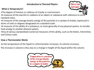
Primary Mechanic of Heat Transfer • Thermal energy transport: cause by temperature difference, high T -> low T • Conduction Heat transferring by solid medium • Convection Transferring energy between solid surface and fluid Mass transport Natural (free) convection Forced convection • Radiation Heat transferring by electromagnetic waves
Conduction • Fourier’s Law Q= -KA ΔT/ΔL Q: heat transfer rate A: cross-sectional area of heat flux ΔT/ΔL: temperature gradient K: thermal conductivity (W/mk) Ex. Al = 230 Cu = 380 Mylar = 1.8
Convection • Newtonian cooling Law Qc = hc As (Ts – Ta) Qc: convection heat transfer rate As: surface area Ts: surface temperature of solid Ta: tmperature of ambient hc: heat transfer coefficient, f(flow type, body geometry, physical property, temperature, velocity, viscosity…) • Natural convection & Forced convction hc of air, natural convection: 0.0015~0.015 W/in2℃ forced convection: 0.015~0.15 W/in2℃
Radiation Qa = εσAF1-2( Ts4– Ta4) Qa: radiation heat transfer rate ε: emissivity, 0 ≦ε≦ 1 σ: Stefan-Boltzmann constant A: surface area F1-2: view factor Ts: temperature of body s Ta: temperature of body a
Thermal Resistance • R = V / I V: voltage = ΔT: temperature difference I: current = Q: heat • Conduction Rk = ΔL/KAk • Convection Rs = 1 / hcAs • Radiation Ra = (Ts – Ta) /εσAF1-2( Ts4– Ta4)
Basic Concepts for NB Thermal Design • Thermal Design Target Thermal design must meet thermal spec. of CPU, all key components (HDD, FDD, CD-ROM, PCMCIA…), and all IC chips (Chipset, VGA, RAM, PCMCIA…), and all IC chips (Chipset, VGA, RAM, Audio…) in each user conditions • Thermal Resistance Θj-a = (Tj – Ta) / Pcpu Θ j-a : CPU junction to ambient thermal resistance Tj: CPU junction temperature Ta: ambient temperature Pcpu: CPU power
Basic Concepts for NB Thermal Design • System Thermal Coupling effect Θj-a = (Tj – Ta – Tsys) / Pcpu Tsys: system temperature = Psys *Θ = ΣPi*θi, (i: DRAM, Chipset, HDD, FDD, CD-ROM…) R: thermal coupling factor between Pcpu and Psys Tj: CPU spec. for Intel: 100℃ Ta: OEM spec., 35℃ Θj-a, Tsys: OEM design dependent, Tsys = 10~15℃
Basic Concepts for NB Thermal Design • Thermal Solutions • Passive thermal solution • Active thermal solution • Hybrid thermal solution • RHE • Remote Heat Exchanger
Basic Concepts for NB Thermal Design • Characteristic of a good passive components • Spreader plate connected to CPU should be as large as possible • Temperature variation on spreader plate should be minimal • Characteristic of a good active component • Air inlet and outlet should be clearly defined • Length of air passage through NB should be small to keep pressure drop low, flow rate high • Possible reduce noise level of the fan • Design must be capable of venting a portion of hot air from NB inside
Important Components For Thermal Design • Heat Sink • Heat Pipe • Fan • TIM ( Thermal Interface Material) • Combination of aforementioned components
Heat Sink • Material Material : A1050 A6063 ADC12 C1100 K(W/mk) : 230 210 192 384 Specific gravity: 2.71 2.69 2.70 8.92 • Production Die-casting Extruded • Q = -KAΔT/ΔL • Fin, Q = hAΔT Die-casting, extrusion, folder, stack, soldering fins
Heat Pipe • Basic configuration and characteristic • Basic specification Material: copper Working fluid: pure water Standard working temperature: 0~100℃ Size: ψ3, ψ4, ψ5, ψ6, ψ8 • Typical heat pipe wick structures Fiber, mesh, groove, powder • Typical modification of heat pipe Flattening Bending • Heat Plate
Fan • Structure • Rotator: magnetic blade, shaft • Stator: bearing, wire, stainless plate • Control circuit • Theory • Type • Axial fan • Blower fan • Selection • Total cooling requirement Q = Cp * m * ΔT = ρ* Cp * CFM * ΔT • Total system resistance / system characteristic curve • System operating point
Fan • Parallel and series operation • Acoustical noise level (dB) To achieve low noise should consider • System impedance • Flow disturbance • Fan speed and size • Temperature rise • Vibration • Voltage variation • Design considerations
TIM • Thermal Interface Material • To reduce contact thermal resistance between CPU die and thermal module • Important of TIM • Material • Various material: silicon-base, carbon… • Non-phase change • Phase change • Pressure effect • Pressure spec. on CPU spec. 100psi
Clarify Thermal Specification Evaluate heat generation Allowable thermal resistance Allowable design space Design Thermal Solution Design Thermal Solution Evaluate Chassis heat dissipation Evaluate heat exchange area Evaluate fan flow rate Analytic Approach Evaluate Solution Performance NumericalApproach Experiment Approach Verify Fail Pass Thermal Design Procedure
Inspect Structure.Production method.Cost… Recommend Thermal Solution Thermal Test in Working Sample Examine and Modify Thermal Solution Verify Overall System Meeting Thermal Specification Fail Pass Thermal Design OK!
Thermal Design Guides Design guide for thermal (Ver. 0.2)
細絲(銅絲) 螺旋彈片 fiber Mesh 銅网
直接加工而成 groove Powder 類型: 金屬粉末燒結在Heat Pipe內壁, 形成毛細結構
N 無刷馬達轉動原理 N 有Hall IC 感應其磁鐵N.S.極, 經由電路控制其線圈之導通產生內部激磁使轉子部旋轉 S S S S N N
Static pressure Fan curve System resistance curve System operating point CFM(ft3/min)
Thermal Module • Reserve space for thermal module (Intel recommendation) Coppermine: 70*50*11.5mm Tualatin: 75*55*11.5mm Northwood: 85*60*19mm • It should reserve a gap between thermal module and top cover (keyboard cover)
1. Thermal Module • The gap between thermal module exit and NB case vent should be sealed well so the hot air couldn’t flow back to system. If leave an open gap along air flow path, it will affect thermal efficiency and acoustic noise.
1. Thermal Module • The thermal module and CPU should contact well. • The max pressure of the thermal module on CPU is 100psi. Within SPEC, efficiency of thermal module increases with pressure. • It’s better to fix module on M/B by four screws (avoiding three screws) and spring design.
2. Fan • Fan inlet constraints: gap 3~5mm is needed. 3mm ~ 80% performance 4mm ~ 90% performance 5mm ~ 100% performance • Configuration of air inlet & outlet vents can make dramatically flow resistance; therefore high open rate is better.
2. Fan • Don’t place blocks (large ICs or connector) near or below the fan to affect airflow induced into fan. • It is better for fixing fan by rubber instead of metal screws to avoid vibration.
2. Fan • The fan space design has some restrictions. • For efficiency and acoustic, the gap between fins and fan blade should keep a distance of L= 5 ~ 10 mm. • The distance W is better to keep as large as possible for good efficiency. • Fan blade should close to fan tongue for better efficiency.
3. PCMCIA Card • Don’t place PCMCIA on lower side of M/B, near hotter ICs, and stacked up key components (HDD, CD-ROM, DVD, FDD…). • If it needs to place PCMCIA near heat source, it is necessary to induce airflow to cool it. (Ex. For J2I++, L1R, it is removed metal plate on PCMCIA slot and makes holes above PCMCIA if there is an Al plate upon it. By this way, air can flow through this area to cool PCMCIA card.)
3. PCMCIA Card • Due to aforementioned solution, PCMCIA should place near fan in order to induce airflow to cool.
4. Key Components • Because HDD, CD-ROM, FDD thermal SPCE is low, these key components need to be placed in colder region. (Avoid placing them in the middle of the system and upon M/B with hot ICs, and stacking up each other). • It’s better to place FDD alone, not to put on/beneath CD-ROM or HDD.
5. Palm-Rest and Glid Pad • It should avoid placing hot components and ICs below palm-rest and glid pad. • It should reserve a gap to make a thermal resistance between palm-rest and the hot components or to add a metal plate for spreading heat.
6. LCD Inverter It should reserve a gap between Inverter and LCD cover to make a thermal resistance or to add a metal plate for spreading heat.
7. Bottom case and Dimm Door • It should reserve a gap between IC chips and bottom case(gap > 3mm is better). • It might have a large Al-plate on bottom case for spreading heat. • M/B has a hole below fan in order to induce airflow under M/B. • It’s better to place hotter chips on upper side of M/B. • It should reserve a gap between Memory chips and dimm door (gape > 1.5mm is better).
8. M/B Layout • If there’s thermal issue of ICs, it should reserve space for thermal solutions (Ex. Don’t place higher components beside these ICs, so it could put metal plate on ICs in future) • Don’t place low temperature spec ICs and components near hotter region or high temperature spec ICs and components.
9. Others • It’s better to use the thinner or phase change TIM (thermal interface material) Ex. 28W CPU (phase change) Powerstrate 0.08mm 75℃ (phase change) T-pcm 0.25mm 83℃ T-pcm 0.50mm 86℃ (phase change with Al) T-mate 0.50mm 83℃ (non-phase change) Tx 0.25mm 90℃ Tx 0.5mm 96℃
9. Others • Heat pipes on thermal module have some restrictions • The thickness shouldn’t be less than 2mm when be made flat. • The curve radius should be larger than triple diameter at least when be bended. • It might need some holes on bottom case and sidewall of NB in order to induce airflow to dissipate heat.
Fan 3mm ~ 80% performance 4mm ~ 90% performance 5mm ~ 100% performance Air flow 3~5mm
Fan Bad design Blocks
Tongue L: 太大, Fan效率下降; 太小, 噪音上升. L W 該縫隙越小Fan 效率越高, 但Noise 也會隨之上升 W: 作為風道, 盡量大
Pressure Single fan Parallel Double fan CFM Pressure Single fan Series Double fan CFM
TIM: thermal interface material • 考慮將散熱器固定於發熱器件的方法時, 重要的是要使二者之間界面熱傳到處效率最大. • 也應考慮其他要求, 如介電特性, 電導性, 附著強度和再次安裝的可能性. • 發熱組件和散熱器之間界面的熱傳輸效率取決於空氣殘留, 填充物類型和黏合曾的厚度等參數.