Download
1 / 17
1k likes | 2k Views
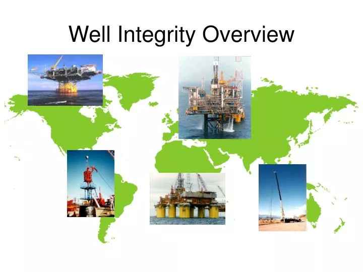
Well Integrity Overview. Well Integrity – what does it all mean!. Definition of Well Integrity.

E N D
Well Integrity – what does it all mean! Definition of Well Integrity Well Integrity is the Design, Installation, Operation and Maintenance of all Well Equipment to a standard that ensures the Safe Containmentof Produced Well Fluids & Injectants for the Life of the well. Keep the hydrocarbons in the pipe ! Why is Well Integrity Important? It’s about the safety of people, our equipment and our business
This is what we want to avoid! Why is Well Integrity Important? It canhelp to prevent incidents like this
Safety Statutory regulations Internal Policy & Standards Production Reputation Technical & Performance Standards Procedures Industry Standards Vendors Procedures Knowledge , Training & Competency Integrity Drivers & Implementation
Well Construction Principles • Generally a well will consist of conductor, casing, tubing, wellhead and Christmas tree. • The conductor protects the casing from seabed to platform surface, and provides a stable support for the wellhead and Christmas tree. • Three or four strings of casing will be run inside the conductor, with diminishing I.D’s • Typically 30” conductor. • 20” Surface Casing • 13.3/8” Intermediate Casing • 9.5/8” Production Casing • 7” Liner
1 3 9 11 2 4 5 8 6 7 10 12 Casing Design : Basic Construction • 30” conductor • Conductor setting depth • 20” surface casing • 20” shoe • Cement • Formation open to C annulus • 13 3/8” casing • Formation open to B annulus • 9 5/8” production casing • Liner hanger • 7” Liner • TD – Total Depth
1 2 4 7 9 10 11 3 5 6 12 8 Completion Components – What’s installed • Tubing hanger (Upper annulus barrier) • SC-SSSV (Sub-surface barrier) • Control line • Tubing (Vertical barrier) • A annulus (tubing-casing) • Gas lift valves (in SPMs) • Expansion joint: Tubing Seal Receptacle • Anchor seal assembly • Production packer • Packer sealing element (Lower barrier) • Tailpipe • WEG 9 5/8” Production Casing
1 2 4 7 9 10 11 3 5 6 12 8 Completion Components – Why? Function : • Upper annulus barrier & supports tubing • Protects the surface installation • Hydraulically operates the SC-SSSV • Conveys hydrocarbons to surface • Protects production casing from attack • Permit entry of lift gas annulus to tubing • Accommodates expansion / contraction • Ties & seals tubing string to packer • Anchors tubing string to production csg • Forms lower barrier of the A annulus • Allows installation of instrumentation • Easy entry of production logging tools back into tailpipe 9 5/8” Production Casing
Annular Safety Valve - Gas Lift • The ASV contains large amounts of pressurised gas in the tubing-casing annulus – should the well-head become damaged • An 8,500 ftannulus contains large quantities of lift gaswhen pressured up to 1800 psi • Provides annular by-pass via a hydraulically operated valve array Lift Gas
Annular Safety Valve - Closed ASV in Closed Position Evacuated Lift Gas • Lift gas above ASV escaped to surface following loss of surface systems integrity • Lift gas retained in A annulus below ASV
The Well Integrity Envelope DHSVs - Regular integrity & function testing Xmas Trees - Regular Maintenance and Testing Annuli – Regular monitoring & reporting Report and Action if set criteria do not meet expectations. Integrity Drivers Integrity Drivers
Why monitor annuli pressures ? Definition : “the area between two concentric circles” “a ring shaped part , figure or space” • The annular voids form the principal barriers between the produced fluids and the atmosphere. • By monitoring the annulus pressures we are able to assess the condition and integrity of the well tubulars. • Anomalous annulus pressures may give the first indication of down hole problems although it does not automatically mean there is a leak • Thermal expansion or ingress of formation fluid could also cause an increase in annulus pressure, regular sampling of annulus fluids may also be undertaken • Annulus temperatures should also be considered
Tubing, Annulus & Formation Temperature Cool Hot Annulus Monitoring - Well Start-up C A B A C B Tbg A B C Formn Depth Formation Increasing distance from tubing