Download
1 / 57
740 likes | 1.29k Views
The Boundary Element Method (and Barrier Designs). Architectural Acoustics II March 31, 2008. Barrier Designs. Barrier Designs. Barrier Designs. Barrier Designs. Barrier Designs. Barrier Designs. Barrier Designs. Barrier Designs. Barrier Designs. Barrier Designs. Barrier Designs.

E N D
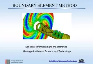
The Boundary Element Method(and Barrier Designs) Architectural Acoustics II March 31, 2008
BEM: Outline • Review • Complex Exponentials • Wave equation • Huygens’ Principle • Fresnel’s Obliquity Factor • Helmholtz-Kirchhoff Integral • Boundary Element Method • Relationship to Wave-Field Synthesis
References • Encyclopedia of Acoustics, M. Crocker (Ed.), Chapter 15, “Acoustic Modeling: Boundary Element Methods”, 1997. • Acoustic Properties of Hanging Panel Arrays in Performance Spaces, T. Gulsrud, Master’s Thesis, Univ. of Colorado, Boulder, 1999. • Boundary Elements X Vol. 4: Geomechanics, Wave Propagation, and Vibrations, C. Brebbia (Ed.), 1988. • Boundary Element Fundamentals, G. Gipson, 1987. • “Assessing the accuracy of auralizations computed using a hybrid geometrical-acoustics and wave-acoustics method,” J. Summers, K. Takahashi, Y. Shimizu, and T. Yamakawa J. Acoust. Soc. Am. 115, 2514 (2004).
Complex Exponentials In general: For the upcoming derivation:
Wave Equation • Hyperbolic partial differential equation • Partial derivatives with respect to time (t) and space ( ) • Can be derived using equations for the conservation of mass and momentum, and an equation of state
Huygens’ Principle (From 1690): Consider a source from which (light) waves radiate, and an isolated wavefront created by the source. Each element on such a wavefront can be considered as a secondary source of spherical waves, and the position of the original wavefront at a later time is the envelope of the secondary waves. Christiaan Huygens (1629 – 1695)
S Huygens’ Principle Point source S emitting spherical waves.
S Huygens’ Principle Secondary sources on an isolated wavefront.
S Huygens’ Principle Spherical wavelets from secondary sources.
S Huygens’ Principle This is the problem with the original Huygens’ Principle. Envelope of wavelets: outward inward
S Huygens’ Principle Envelope of wavelets, outward only.
Fresnel Huygens-Fresnel Principle (1818): Fresnel added the concept of wave interference to Huygens’ principle and showed that it could be used to explain diffraction. He also added the idea of a direction-dependent obliquity factor: secondary sources do not radiate spherically. Augustin Fresnel (1788 – 1827)
Kirchhoff Kirchhoff showed that the Huygens-Fresnel Principle is a non-rigorous form of an integral equation that expresses the solution to the wave equation at an arbitrary point within the field created by a source. He also explicitly derived the obliquity factor for the secondary sources. Gustav Kirchhoff (1824 - 1887)
Helmholtz Namesake of the Helmholtz equation and a huge contributor to the science of acoustics. Hermann von Helmholtz (1821 - 1894)
Secondary sources have cardioid pattern: Fresnel’s Non-Spherical Secondary Sources θ θ S
Secondary sources have cardioid pattern: Fresnel’s Non-Spherical Secondary Sources S
Secondary sources have cardioid pattern: Fresnel’s Secondary Sources - + Monopole Dipole Cardioid - =
Helmholtz Equation • Start with the wave equation • Assume p is time harmonic, i.e. • Then the wave equation becomes the Helmholtz Equation: • k = ω/c is the wave number
Green’s Functions • To represent free-field radiation, we need the function • G is called a “Green’s Function” (after George Green (1793-1841)) • A Green’s Function is a fundamental solution to a differential equation, i.e. where L is a linear differential operator • In this case (the Helmholtz equation), r = dist. between Q and P
Interior Problem (Room Modeling) Exterior Problem (Object Scattering) V Source Q V n r S S n r Q Source Two Applications V = volume S = surrounding surface n = surface normal Q = receiver r = distance from Q to a point on S
0 Helmholtz-Kirchhoff Integral • Start with these equations • Multiply (1) by G and (2) by p • Subtract (3) from (4) (1) (2) (3) (4) (5)
Helmholtz-Kirchhoff Integral • From the previous slide • Integrate over the volume V • Apply Green’s Second Identity • The result is the Helmholtz-Kirchhoff Integral
Helmholtz-Kirchhoff Integral • From the previous slide • Recall • So
Src. Rec. (Q) r dS Surface S Helmholtz-Kirchhoff Integral p(Q) = sound pressure at receiver point Q = 2f = frequency of sound (f = frequency in Hz) pS = sound pressure on the surface S n = surface normal k = /c = wave number c = speed of sound r = distance from point on S to Q
Helmholtz-Kirchhoff Integral The Helmholtz-Kirchhoff integral describes the (frequency domain) acoustic pressure at a point Q in terms of the pressure and its normal derivative on the surrounding surface(s). The normal derivative of the pressure is proportional to the particle velocity.
Helmholtz-Kirchhoff Integral →Boundary Element Method • HK Integral gives us the (acoustic) pressure at a point Q in space if we know the pressure p and normal velocity δp/δn everywhere on a surrounding closed surface • For the BEM, we • Discretize the boundary surface into small pieces over which p and δp/δn are constant • Calculate p and δp/δn for each patch • Use the patch values to calculate p(Q)
BEM Details • Discretization changes the integral to a summation over patches • Patches can be rectangular, triangular, etc. • Each patch can be defined by multiple nodes (e.g. for a triangle at the three corners and the center) or just one at the center • Multiple nodes per patch: interpolate p and δp/δn between them • One node per patch: p and δp/δn are assumed to be constant over the patch • Patches/node spacing must be smaller than a wavelength so p and δp/δn don’t vary much over the patch • Typically at least 6 per wavelength, so high-frequency calculations are prohibitively expensive computation-wise • There are several methods to find p and δp/δn
Simplest Solution: The Kirchhoff Approximation • At each patch, let p = RRefl·PInc • RRefl = surface reflection coeff. • PInc = incident pressure • Surface velocity found in a similar way • Surface conditions are due to source only. No patch-to-patch interaction! • Useful only for the exterior problem
Proper BEM • To make this easier, we’ll make two assumptions • The surface is rigid, so δp/δn = 0 • We have one node per patch (at the center) • A surface with N patches and N nodes • So, we have Image from “Sounds Good to Me!”, Funkhouser, Jot, and Tsingos, Siggraph 2002 Course Notes
BEM • Create N new receivers and place one at each node on the surface • So for receiver j we have • And a set of N linear equations in matrix form Direct sound at receiver j Influence of other patches on j where
BEM • But since each receiver is on the surface • So where I is the identity matrix This is why BEM is only useful at low frequencies and/or for small spaces. F is an n x n matrix, and matrix inversion is ~O(n2.4)!
BEM • Now we have the pressure at each node/patch, specifically the N-element vector • Use the values in psurf to find p(Q) using our original equation
Results A new analysis method of sound fields by boundary integral equation and its applications, Tadahira and Hamada.
Results A new analysis method of sound fields by boundary integral equation and its applications, Tadahira and Hamada.
Results Prediction and evaluation of the scattering from quadratic residue diffusers, Cox and Lam, JASA 1994.
M M + Hybrid BEM/GA Modeling CATT-Acoustic 100 Hz Sysnoise BEM 100 Hz IFFT J. Summers, K. Takahashi, Y. Shimizu, and T. Yamakawa, “Assessing the accuracy of auralizations computed using a hybrid geometrical-acoustics and wave-acoustics method,” 147th ASA Meeting, New York, NY, May 2004.
X X X X Test Case: Assembly Hall at Yamaha Summers et al. 2004
Test Case: Assembly Hall at Yamaha • Why this space? • Reasonable size allows for tractable BEM • Easy access for measurements and surface impedance measurement • Existing computer model • Model details • 11180 linear triangular elements • Δl = 0.64 m • f = 10 – 100 Hz • elements / λ ≥ 5 for all frequencies Summers et al. 2004
Results: Time Domain GA+BEM GA Measured 63 Hz octave band Summers et al. 2004