Download
1 / 16
160 likes | 449 Views
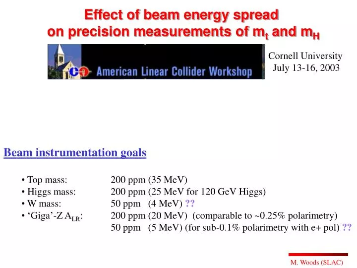
Effect of beam energy spread on precision measurements of m t and m H. Cornell University July 13-16, 2003. Beam instrumentation goals Top mass: 200 ppm (35 MeV) Higgs mass: 200 ppm (25 MeV for 120 GeV Higgs) W mass: 50 ppm (4 MeV) ??

E N D
Effect of beam energy spread on precision measurements of mt and mH Cornell University July 13-16, 2003 • Beam instrumentation goals • Top mass: 200 ppm (35 MeV) • Higgs mass: 200 ppm (25 MeV for 120 GeV Higgs) • W mass: 50 ppm (4 MeV) ?? • ‘Giga’-Z ALR: 200 ppm (20 MeV) (comparable to ~0.25% polarimetry) • 50 ppm (5 MeV) (for sub-0.1% polarimetry with e+ pol) ??
The beam energy spectrometers measure <E>, but for physics we need to know <E>lum-wt. Effect I am considering today is the beam energy spread. At NLC, s(E) ~ 0.3% rms, and at TESLA it is ~ 0.1% rms. (3000 ppm) (1000 ppm)
Energy Spread Study • MatLIAR-generated files from Andrei Seryi • LIAR+DIMAD+Matlab used to generate files • Tools developed by NLC Accelerator physics group • Files were used for TRC studies • They were obtained with non-perfect machines: • LCs were initially misaligned and then brought • back to ~nominal luminosity by one-to-one • correction in the linac. • generates distributions of incoming beams at IP • 6 files each for NLC-500 and TESLA-500 machines • Electron and positron beams are symmetric; • ie. similar spotsizes, bunch lengths, charge • Guinea-Pig simulation • ISR and Beamstrahlung turned off • electron.ini and positron.ini files from MatLIAR simulation • beam1.dat and beam2.dat files for outgoing beam distributions • lumi.dat file for distribution of particles that make luminosity
NLC-500 Results Tail Head
Summary of Results for energy spread effect Note: energies are given in units of ppm, ie. the deviation from the nominal energy, for example: E1, E2 and Ecm all come from The Guinea-Pig file lumi.dat ~500ppm effect for NLC ~ 50ppm effect for TESLA
Kink instability is dominant cause for energy bias effect • tail of the bunch is disrupted in y • energy-z correlation of the incoming bunches exacerbates effect • Can consider collision of opposing bunches to be: • head-head collisions (high ECM) • head-tail collisions (nominal ECM) • tail-tail collisions (low ECM; lower luminosity due to disruption) • Why effect is larger for NLC than TESLA: • large E-z correlation results from having to reduce • wakefields in the warm machine by performing a phase • space rotation to shorten the bunch length and increase • the energy spread • large energy spread (for same reason to mitigate wakefields)
Comparing “kink instability” for e+e- and e-e- at NLC-500 e+e- e-e- (NLC-G has beam parameters with uncorrelated, gaussian distributions)
Comparing “kink instability” for e-e- at NLC-500, TESLA-500 e-e- e-e-
“kink instability” for e-e- at NLC-500; effect of E-z correlation • With E-z • correlation e-e- 2. Without E-z correlation (made z dist’n uncorrelated with 120 mm rms) e-e-
e+e- (NLC-6) Outgoing e- Outgoing e- Lumi-wted ECM Outgoing e-
e-e- (NLC-6) Outgoing e- Outgoing e- Lumi-wted ECM Outgoing e-
Y Deflection Scan (deflection angles) NLC-6 e+e- TESLA-6 e+e- NLC-6 e-e- TESLA-6 e-e- ‘sharp’ deflection curve will make beam-based feedback/feed-forward difficult
Y Deflection Scan (luminosity) NLC-6 e-e- TESLA-6 e-e- NLC-6 e+e- TESLA-6 e+e-
Y Deflection Scan NLC-6 e-e- NLC-6 e-e- Maximum luminosity occurs at zero deflection angle, not zero offset
Summary • Kink instabilityreduced luminosity • bias in energy determination • - large for e+e- at NLC due to large • E-z correlation and large espread • - large for e-e- at both NLC and TESLA • minimizing deflection angle reduces effect • Energy bias for e+e- collisions at NLC is ~500ppm • large compared to desired precision on energy determination of <200ppm • need to understand associated systematics and compare to other sources • need to see if 500ppm effect can be reduced • For e-e- collisions at NLC and TESLA • deflection scans indicate that beam-based feedbacks will be difficult • need to find more optimal collision parameters than those used for e+e-