Download

1 / 71
720 likes | 1.35k Views
Public Safety Radio Bands. VHF-Low Band: 25 MHz to 50 MHz VHF-High: 138 MHz to 174 MHz UHF: 408 MHz to 512 MHz 700 MHz (new) 800 MHz 4.9 GHz (new). Why is this a problem?. Radios only operate in one band! Multi-band radios are rare and expensive

E N D
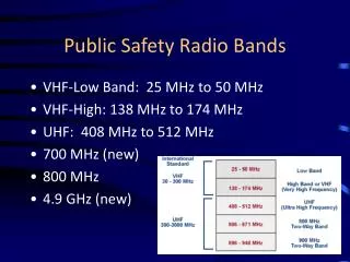
Public Safety Radio Bands • VHF-Low Band: 25 MHz to 50 MHz • VHF-High: 138 MHz to 174 MHz • UHF: 408 MHz to 512 MHz • 700 MHz (new) • 800 MHz • 4.9 GHz (new)
Why is this a problem? • Radios only operate in one band! • Multi-band radios are rare and expensive • If Agency A uses VHF and Agency B uses UHF, they can’t talk to each other UNLESS… • …They have planned ahead! • Two radios in a rig, etc.
Propagation Basics- Free Space Path Loss • Path Loss (in dB) = 36.6+20xLog[D]+20xLog[F] • Where: D is distance in miles F is frequency in MHz • So: as frequency increases, path loss increases • This means that if everything else were equal, a system at a lower frequency would reach farther than a system at a higher frequency • But…other factors are at play as well
Propagation & Band Characteristics • VHF Low Band (30-50 MHz) • Best propagation in undeveloped and hilly terrain–Poor building penetration • VHF High Band (150-174 MHz) • Very good propagation in undeveloped and hilly terrain–Moderate building penetration • UHF (450-512 MHz) • Good propagation in undeveloped and hilly terrain–Good building penetration • 700/800 MHz • Poor propagation in undeveloped and hilly terrain–Very good building penetration– • 700 currently subject to incumbent television stations in some areas • 800 currently subject to interference from commercial carriers • 4.9 GHz • Microwave propagation used for short range (Wi-Fi type) or point-to-point links
Frequencies vs. Channels • A frequency is a point in the radio spectrum • part of what describes a channel • A channel is a set of parameters that can include one or more frequencies, CTCSS tones, name, etc. • Example: VCALL is a channel with transmit and receive frequency 155.7525 MHz, CTCSS tone of 156.7 Hz
CTCSS (PL) Tones • PL stands for Private Line, a Motorola trademark • Other names include Code Guard, Tone Squelch, Call Guard, Channel Guard, Quiet Channel, Privacy Code, Sub-audible Tone, etc. • “Generic” term is CTCSS – Continuous Tone Coded Squelch System
What Are These Tones? • A PL tone is a sub-audible (barely audible) tone that is sent along with the transmitted audio • A receiver that has CTCSS decode (a.k.a. a receive PL tone) activated will only open its speaker if the correct tone is received • PL tones are different than tones used to set off pagers (two-tone sequential paging) • Remember…PL tones are sub-audible and continuous…they are being sent the entire time a radio is transmitting
What Are They Used For • PL Tones are used to MASK interference • They DO NOT REMOVE INTERFERENCE • Useful for masking interference from computers, electronics, etc. • Useful for masking interference from “skip” • Should NOT be used to block out traffic from neighboring (nearby) departments • This is OK for taxis, etc., but not for public safety • Creates “Hidden Interference” problem – missed calls possible
What Are They Used For (cont.) • Used to activate remote links • Used to access repeaters
DCS – Digital Coded Squelch • A.k.a. Digital Private Line (DPL) • Similar to CTCSS, but uses a digital code instead of an audio tone • Used on analog radio systems, even though it is a digital code
Encode vs. Decode • PL (or DPL, et.c) Encode means to transmit the tone • Decode means that the receiver will listen for the tone and not let anything through unless the correct tone is received • TX and RX tone can be different • Radio can be set to TX tone but have no RX tone (all traffic is received) • If in doubt, don’t program RX tone • “Monitor” function bypasses RX tone
Results of Improper Programming • If Radio 1 is set for TX tone only and Radio 2 is set for TX/RX, both radios will hear each other. Radio 1 will hear any interference on the channel • If Radio 1 is set for TX tone only and Radio 2 is set for no tone, both radios will hear each other. Both radios will hear any interference on the channel • If Radio 1 is set for TX/RX tone and Radio 2 is set for TX/RX tone, both radios will hear each other. • If Radio 1 is set for TX/RX tone and Radio 2 is set for no tone, Radio 1 will not hear Radio 2. Radio 2 will hear Radio 1 • ANY radio programmed with an incorrect TX tone will not be heard by radios using a RX tone, even though it can hear traffic from other radios
Simplex • Very Reliable • Limited Range • Radio Channel uses 1 frequency
Duplex • Radio Channel using 2 frequencies, Freq 1 to talk from radio A to radio B, and Freq 2 to talk from radio B to radio A • Each user must be line of sight with each other • Examples: Cordless Telephone systems, which both parties can talk at the same time and listen at the same time. f1 f2
Base Station – Height Improves Range Dispatch Center Some units don’t hear transmission because of obstructions Unit 1 Unit 4 Unit 2 Unit 3
Base Station – Height Improves Range Dispatch Center Dispatcher relays message – heard by all units Unit 1 Unit 4 Unit 2 Unit 3
Remote Base Operation Dispatch Center Remote Link Microwave, Phone Line, etc. Unit 1 Unit 4 Unit 2 Unit 3
Conventional Repeater • Receives a signal on one frequency and retransmits (repeats) it on another frequency • Placed at a high location • Increases range of portable and mobile radio communications • Allows communication around obstructions (hills, valleys, etc.) • User radios receive on the repeaters transmit frequency and transmit on the repeater’s receive frequency (semi-duplex)
Conventional Repeater RX TX f2 f1 Dispatch Center All units within range of repeater hear all transmissions through the repeater f2 f2 f2 f2 f1 Unit 1 Unit 4 Unit 2 Repeater Unit 3
Conventional Systems When one user is talking, other users on that channel are cannot talk, even though other repeaters in the area may be idle. Communicating PD 1 PD 4 Idle PD 3 cannot talk to PD 4 because PD 1 is using the repeater PD 2 PD 3 Idle FD 3 FD 1 Public works repeater may be idle 90% of the time, which means that frequency is largely wasted PW 1 FD 2 PW 3 PW 2
Trunking • Trunking is a method of combining repeaters at the same site to “share” frequencies among users • Spectrally efficient • Allows many more “virtual” channels (called talkgroups) than there actually are frequencies • Computer controlled
PD 3 PD 1 PD 2 FD 2 FD 1 RX RX RX TX TX TX f1 f3 f5 f2 f4 f6 Trunked System f3 f1 f4 f2 f2 • Frequencies are dynamically assigned by system controller • User radio may be on a different frequency every time it transmits • Talkgroups are “virtual” channels • Possible to have many more talkgroups than actual frequencies • Statistically, not all talkgroups will be active at the same time System Controller Shared Repeater Bank
Trunked System Operation • User radios continuously monitor a dedicated “control channel” • When a user wants to transmit, the user’s radio makes a request to the system controller • If a repeater is available, the system controller temporarily assigns that repeater channel to the talkgroup making the request • Transmitting user’s radio will give a “talk beep”, indicating that a repeater has successfully been assigned…user can talk • All user radios monitoring that talkgroup automatically switch to the frequency of the assigned repeater and hear the transmission • When the transmission is complete, all radios return to monitoring the control channel
Multi-Site Systems • Conventional • Repeaters on same output, different input • Linked repeaters on different frequencies • Remote Receive Sites • Voting • Simulcasting • Trunking • Roaming • Simulcasting
Repeaters on same output frequency, different input frequency (or PL tone) Only one repeater active at a time Users must manually change channel to different repeater depending on their physical location
Repeaters on same output frequency, different input frequency (or PL tone) Only one repeater active at a time Users must manually change channel to different repeater depending on their physical location
Linked repeaters on different frequencies Both repeaters active at the same time with same traffic, but on different frequencies Link (microwave, phone line, etc.) Users must manually change channel to different repeater depending on their physical location
Voting Receivers Voter (comparator) chooses best received signal and sends that signal to the transmitter Voter Central Transmitter Link (microwave, phone line, etc.) RX Only Site Users do not need to change channel depending on location. System (voter) automatically picks best receive tower site.
Simulcasting Both repeaters transmit at the same frequency at the same time Link (microwave, phone line, etc.) Transmitters must be carefully synchronized to prevent interference in overlap areas
Radio Wave Polarization • Two-way radio systems use vertical polarization (antenna elements are oriented vertically) • Cross-polarization results in signal loss (can be very dramatic) • What does this mean? Hold portable radio so that antenna is oriented vertically…don’t hold it sideways!!
Antenna Gain • Gain refers to how power is transmitted in different directions from an antenna • An antenna with no gain (0 dBi, or dB relative to an isotropic radiator) radiates an equal amount of power in all directions • An antenna with some gain (say 3 dBi) radiates 3 dB more power in one direction than the o dBi antenna, but this means that less power is radiated in another direction • The amount of power transmitted doesn’t change due to antenna gain…where the power is transmitted changes (think of squeezing a balloon) • Gain is only useful if the antenna is pointed at the target (Think TV antenna)
Isotropic & Dipole Radiation Patterns Dipole Together Isotropic
Dipole Antenna Radiation Pattern Source: http://www.tpub.com/content/neets/14182/css/14182_186.htm
Omnidirectional “gain” antenna radiation patterns over ground
Highly Directional Antenna Radiation Pattern Relative to Isotropic Relative to a Dipole
Why does gain matter? • Antenna orientation matters • “High gain” antennas send more energy towards horizon, less into the air (good for ground comms, bad for air-ground) • Radiation patterns are greatly affected by the antenna ground plane and nearby metal • For best performance, mobile antennas should be mounted in the center of the roof
Common Analog Modulation Schemes • FM – Frequency Modulation • AM – Amplitude Modulation • SSB – Single Sideband AM • Almost all analog public safety communications use FM • AM is used for CB radio, aircraft communication
Frequency Modulation (FM) • To modulate means “to change” or “to vary” • Frequency Modulation means changing the frequency of the transmitter in proportion to the audio being picked up by the microphone • The receiver detects the change in transmitter frequency and uses it to reproduce the audio signal at the speaker
Frequency Modulation – An Illustration Microphone Output: Transmitter Output:
FM Radio Block Diagrams(simplified) Transmitter Receiver
Digital Modulation • Signal from microphone is converted from a voltage into numbers through a process called sampling • Those numbers are processed by a computer • Binary information (ones and zeros) is sent over the air instead of analog (continuous voltage) information
Frequency Shift Keying – An Illustration Digital Bitstream: Transmitter Output:
Vocoding • Vocoding is used to reduce the amount of data that needs to be sent over the air • Used to reduce necessary bandwidth – conserves spectrum • “Compresses” digital audio – analogous to .mp3 versus .wav audio files • Uses known human speech characteristics to “fill in gaps” of data that is removed
Digital Radio Block Diagrams(simplified) Transmitter Receiver
The Digital Radio “Problem” • Parametric vocoder uses known human voice characteristics to encode and decode data • When background noise (non-human noise) is present, vocoder doesn’t always know how to respond • Unpredictable results (garble, loss of communication, etc.) • In a similar situation, an analog radio would transmit the background noise right along with the intended audio (background noise might overpower voice, but some audio is still received)