Download

1 / 24
290 likes | 1.02k Views
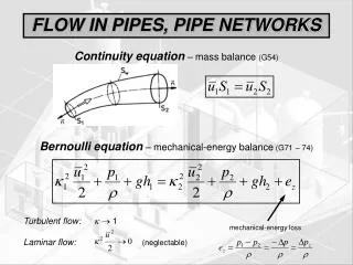
Pipe Networks. Closed Conduit Flow: Review. Energy equation Head loss major losses minor losses EGL and HGL Non circular conduits Pipeline systems pipe networks measurements manifolds and diffusers Pumps. Pipeline systems: Pipe networks. Water distribution systems for municipalities

E N D
Closed Conduit Flow:Review • Energy equation • Head loss • major losses • minor losses • EGL and HGL • Non circular conduits • Pipeline systems • pipe networks • measurements • manifolds and diffusers • Pumps
Pipeline systems:Pipe networks • Water distribution systems for municipalities • Multiple sources and multiple sinks connected with an interconnected network of pipes. • Computer solutions! • KYpipes • WaterCAD • CyberNET
1 2 b Water Distribution System Assumption a • Each point in the system can only have one _______ • The pressure change from 1 to 2 by path a must equal the pressure change from 1 to 2 by path b pressure
a 1 2 b Water Distribution System Assumption • Pipe diameters are constant • Model withdrawals as occurring at nodes so V is constant Pressure change by path a zero Or sum of head loss around loop is _____. (Need a sign convention)
Pipes in Parallel • Find discharge given pressure at A and B • ______& ____ equation • add flows • Find head loss given the total flow • assume a discharge Q1’ through pipe 1 • solve for head loss using the assumed discharge • using the calculated head loss to find Q2’ • assume that the actual flow is divided in the same _________ as the assumed flow Q1 energy S-J Qtotal A B Q2 proportion
A 0.32 m3/s 0.28 m3/s ? a 1 2 Networks of Pipes Mass conservation • ____ __________ at all nodes • The proper relationship between head loss and discharge must be maintained for each pipe • Darcy-Weisbach equation • _____________ • Exponential friction formula • _____________ Swamee-Jain Hazen-Williams b
0.28 m3/s 0.32 m3/s B A 100 m 0.10 m3/s 0.14 m3/s C D 200 m Network Analysis Find the flows in the loop given the inflows and outflows. The pipes are all 25 cm cast iron (e=0.26 mm).
Network Analysis • Assign a flow to each pipe link • Flow into each junction must equal flow out of the junction arbitrary 0.28 m3/s 0.32 m3/s B A 0.32 0.00 0.04 0.10 m3/s 0.14 m3/s C D 0.10
0.28 m3/s 0.32 m3/s 1 B A 2 4 0.10 m3/s 0.14 m3/s C D 3 Network Analysis • Calculate the head loss in each pipe f=0.02 for Re>200000 Sign convention +CW k1,k3=339 k2,k4=169
Network Analysis • The head loss around the loop isn’t zero • Need to change the flow around the loop • the ___________ flow is too great (head loss is positive) • reduce the clockwise flow to reduce the head loss • Solution techniques • Hardy Cross loop-balancing (___________ _________) • Use a numeric solver (Solver in Excel) to find a change in flow that will give zero head loss around the loop • Use Network Analysis software clockwise optimizes correction
Numeric Solver • Set up a spreadsheet as shown below. • the numbers in bold were entered, the other cells are calculations • initially Q is 0 • use “solver” to set the sum of the head loss to 0 by changing Q • the column Q0+ Q contains the correct flows
Solution to Loop Problem Q0+ DQ 0.218 -0.062 -0.202 -0.102 0.28 m3/s 0.32 m3/s 1 B A 0.218 2 4 0.102 0.062 0.202 0.10 m3/s 0.14 m3/s C D 3 Better solution is software with a GUI showing the pipe network.
0.28 m3/s 0.32 m3/s 1 B A 0.218 2 4 0.102 0.062 0.202 0.10 m3/s 0.14 m3/s C D 3 Pressure Network Analysis Software: WaterCAD™ reservoir pipe junction
Network Elements • Controls • Check valve (CV) • Pressure relief valve • Pressure reducing valve (PRV) • Pressure sustaining valve (PSV) • Flow control valve (FCV) • Pumps • Reservoirs • Tanks
open closed Check Valve • Valve only allows flow in one direction • The valve automatically closes when flow begins to reverse
Pressure Relief Valve open closed pipeline relief flow High pipeline pressure Low pipeline pressure Valve will begin to open when pressure in the pipeline ________ a set pressure (determined by force on the spring). exceeds
closed open Pressure Regulating Valve sets maximum pressure downstream Low downstream pressure High downstream pressure Valve will begin to open when the pressure ___________ is _________ than the setpoint pressure (determined by the force of the spring). less downstream
Pressure Sustaining Valve sets minimum pressure upstream closed open Low upstream pressure High upstream pressure Valve will begin to open when the pressure ________ is _________ than the setpoint pressure (determined by the force of the spring). upstream greater
Flow control valve (FCV) flow rate • Limits the ____ ___ through the valve to a specified value, in a specified direction • Commonly used to limit the maximum flow to a value that will not adversely affect the provider’s system
Reservoirs • Are modeled as ________ water level sources • Can supply any demand! constant
Tanks • Obey conservation of mass • Have a finite size • Water level moves up and down and thus _______ in system change! • Need to define tank geometry pressures
Pumps • Require a Pump Curve (discharge vs. head) • Initial setting • Controls for extended time analysis
Water Distribution System • Reservoir - used to model a clear well • Pump to lift water to elevated storage tank • turns on and off based on water level in tank • Tank feeds distribution grid • Demands applied at junctions