Download
1 / 95
1.03k likes | 1.62k Views
2015 SIM TFWG Workshop. Basic Laboratory Calibrations ( Stopwatches and Tachometers ). Luis Mojica Ovalle lmojica@cenamep.org.pa mojica25@hotmail.com Electromagnetic Magnitudes Area CENAMEP AIP. Stopwatch and Tachometer Calibrations. OUTLINE: About the presentation

E N D
2015 SIM TFWG Workshop Basic LaboratoryCalibrations(Stopwatches and Tachometers) Luis Mojica Ovalle lmojica@cenamep.org.pa mojica25@hotmail.com Electromagnetic Magnitudes Area CENAMEP AIP
Stopwatch and TachometerCalibrations OUTLINE: • About the presentation • Stopwatch Calibrations • Device Under Test (DUT) • Traceable Reference • Calibration Method • Calibration Result • Tachometer Calibrations • Device Under Test (DUT) • Traceable Reference • Calibration Method • Calibration Result lmojica@cenamep.org.pa
Stopwatches and TachometersCalibrations REFERENCES: • NIST - Practice Guide Timer Calibrations - 2009 Edition • L. M. Mojica and R. F. Solis, "Error de Tiempo en Cronometros Digitales en Base a Mediciones de Intervalo de Tiempo y Frecuencia," Proceedings of 2011 SEMETRO Conference, Natal, Brazil, 8 p., September 2011. • J. Jiménez and H. Sánchez, "Calibracion de Cronometros Mediante la Medicion de la Frequencia del Oscilador de Cuarzo," Proceedings of 2009 SEMETRO Conference, João Pessoa, Paraíba, Brazil, 3 p., June 2009. • L. Trigo and D. Slomovitz, "Calibración de cronómetros digitales por método de inducción," IEEE Encuentro de Energía, Potencia, Instrumentación y Medidas, Montevideo, Uruguay, pp. 21-23, October 2008. • MSL - Technical Guide 8 - Calibration Stopwatch lmojica@cenamep.org.pa
Why measurement instruments need calibration? ?? Do We make measurements without errors? ?? lmojica@cenamep.org.pa
Stopwatch/Timer Calibrations • Device Under Test (DUT) • Traceable Reference • Calibration Method • Calibration Result lmojica@cenamep.org.pa
Stopwatches/Timers Timers “Time Interval Meters” MechanicalStopwatches Used extensively in industry is the process control timer. Digital Stopwatches Digitalstopwatch have a digital design employing quartz oscillators and electronic circuitry. Mechanicalstopwatches have an analog design and use mechanical mechanisms. Timers, unlike stopwatches, count down from a preset time period instead of counting up from zero. lmojica@cenamep.org.pa
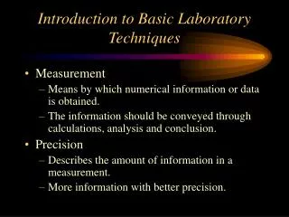
WHAT ABOUT STOPWATCHES AND TIMERS? • Instruments used to measure time interval. • Time interval is defined as the elapsed time between two events. • The standard unit of time interval is the second (s) from NIST - Practice Guide Timer Calibrations - 2009 Edition . lmojica@cenamep.org.pa
WHY WE NEED TO CALIBRATE A STOPWATCH OR LABORATORY TIMER? • Many factors can cause a quartz crystal oscillator to change frequency. from NIST - Practice Guide Timer Calibrations - 2009 Edition. lmojica@cenamep.org.pa
WHY WE NEED TO CALIBRATE A STOPWATCH OR LABORATORY TIMER? • The measurement of time interval is an important parameter in many laboratory or industrial measurements. For example: • Flow measurement • process timing • chemical measurement • and radiological exposure control from MSL Technical Guide 8 - Calibration Stopwatches. lmojica@cenamep.org.pa
Uses of Stopwatches and Timers in Panamá • Inspection and certification of quality oil with emphasis on marine fuels. • To test viscosity oil products: measuring the time it takes to move into a glass capillary. • In creating tablets (medical pills): to control the timing of the various steps in a process called Wet Granulation. • In real-time PCR methodologies: for rapid detection of the presence of pathogenic microorganisms in food (Genetic Detection System Assurance GDS). lmojica@cenamep.org.pa
Some Stopwatch/Timer physical features Every stopwatch is composed of four elements: • Power source • Time base • Counter • Indicator (display). lmojica@cenamep.org.pa
Some Stopwatch/Timer physical Features The design and construction of each component depends upon the type of stopwatch. Interior of digital stopwatch. Interior of mechanical stopwatch. from NIST - Practice Guide Timer Calibrations - 2009 Edition . lmojica@cenamep.org.pa
About of Stopwatch/Timer Especification • Stopwatch • Resolution: • 1/100 second • 1/1000 second • Total elapsed time display: • Times up to 10 hours • 9:59’59.999’’ • 0 to 99 hours, 59 minute, 59 second • Accuracy • ±30 seconds/month 99.9988 % • ± 5 s/day • Timer • Countdown timer: • 100 hours. Count Down/ Up Timer • 99 hours, 59 minute, 59 second to 0 lmojica@cenamep.org.pa
Stopwatch/Timer Calibrations • Device Under Test (DUT) • Traceable Reference • Calibration Method • Calibration Result lmojica@cenamep.org.pa
Like all calibrations, stopwatch and timer calibrations are simply comparisons • Measurementreference are: • a time interval standard or • a frequencystandard • If a time interval standard is used, it is compared to the DUT’s display. • If a frequency standards is used, it is compare to the DUT’s time base oscillator. lmojica@cenamep.org.pa
Examples of Traceable Reference Time Interval References: • Traceable time display. • Time base oscillator. • An traceable audio time signal (usually obtained with a shortwave radio or a telephone). • Since time interval (and not absolute time) is being measured, the fixed signal delay from the source to the user is not important as long as it remains relatively constant during the calibration process. lmojica@cenamep.org.pa
Stopwatch/Timer Calibrations • Device Under Test (DUT) • Traceable Reference • Calibration Method • Calibration Result lmojica@cenamep.org.pa
Generally accepted methods for calibrating a stopwatch or timer • Direct comparison method • Totalize method • Time base method Stop Start Time IntervalReference Measured Time Interval Measurement Error!! lmojica@cenamep.org.pa
Direct comparison method Consists of time interval measurements that compare the time interval display of the DUT to a traceable time interval reference. • The time interval reference is normally a signal broadcast by an NMI, usually in the form of audio tones. DUT Telephone Network lmojica@cenamep.org.pa
Direct comparison method • Advantages: • relativelyeasytoperform: if a telephone is used, does not require any test equipment or standard. • It can be used to calibrate all types of stopwatches and many types of timers, both electronic and mechanical. • Disadvantages: • The operator’s start/stop reaction time is a significant part of the total uncertainty. • It requires long measurement periods. lmojica@cenamep.org.pa
Direct comparison method Three potentially significant sources of uncertainty: • The reaction time of the calibration technician. • The resolution of the DUT. • The uncertainty of the reference. lmojica@cenamep.org.pa
Direct comparison method Sources of uncertainty: • The reaction time of the calibration technician: • The average reaction time of the operator can be either negative (anticipating) or positive (reacting after). • It is recommended that each calibration laboratory perform tests to determine the uncertainty of their operator’s reaction time. lmojica@cenamep.org.pa
Direct comparison method Sources of uncertainty: • The resolution of the DUT: • This method requires observing data from the DUT display. • For digital indicating devices: Resolution uncertainty is one half of the least significant digit (assumed rectangular probability distribution). • For an analog watch: The same method of determining resolution uncertainty may be used because the watch moves in discrete steps from one fraction of a second to the next. Typical Resolution 1/100 second 1/1000 second lmojica@cenamep.org.pa
Direct comparison method • The uncertainty of the reference: Using ordinary land line: • It is recommended that an uncertainty of 30 ms be assigned if the reference signal is one of the telephone services, two phone calls. • Using a not ordinary land line: • It is recommended that an uncertainty of 150 ms be assigned if wireless or VOIP networks are used. • (ITU recommends that delays be kept below this level to avoid the distortion of voice transmissions ) • or 250 ms if calls are routed through a satellite. (Although the use of satellites is now rare) DUT Telephone Network Ordinaryornotordinaryland EmbeddedSystemor PC System lmojica@cenamep.org.pa
Direct comparison method • The uncertainty of the reference (Continuation): Using radio signals: • it is recommended that an Uncertainty often less than 0.01 ms be assigned . if a one hop path becomes a two hop path, the received uncertainty of the radio signal will still not exceed 1 ms. • Using time display: • It can generally be assumed that • the uncertainty of the display is less than1 ms be assigned. • This is because instruments that continuously • synchronize their displays to traceable signals • will normally have repeatable and stable delays. DUT lmojica@cenamep.org.pa
Uncertainty analysis for direct comparison method A example using ordinary land Line * Assuming: Resolution 0.01 s and operators had previous experience calibrating stopwatches. lmojica@cenamep.org.pa
Generally accepted methods for calibrating a stopwatch or timer • Direct comparison method • Totalize method • Time base method Stop Start Time IntervalReference Measured Time Interval Measurement Error!! lmojica@cenamep.org.pa
Totalize method • Partially eliminates the measurement uncertainty from human reaction time. • The time interval reference is generated in the laboratory using a synthesized signal generator, a universal counter, and a traceable frequency standard. • To begin the measurement, start the stopwatch and manually open the gate of the counter at the same time. • The frequency should have a period at least one order of magnitude smaller than the resolution of the stopwatch. lmojica@cenamep.org.pa
Totalize method • Advantages: • Partially eliminates the measurement uncertainty from human reaction time. • Therefore has a lower measurement uncertainty than the direct comparison method. • Disadvantages: • Requires more equipment than the direct comparison method. lmojica@cenamep.org.pa
Totalize method • Source of Measurement Uncertainty: Half of the least significant digit. *Rectangular distribution Ranging from 1×10⁻⁶ to 1×10⁻⁹; cesiumoscillatoror a GPS disciplined Oscillator 1×10-12 or less. • Device Under Test Resolution Uncertainty • Uncertainty of the Frequency Reference ±1 least significant digit on the display. *The counter is simply used as an event counting device • Uncertainty Due to the Counter • Uncertainty Due to Human Reaction Time Example: Mean reaction time 27 ms, Standard deviation 10 ms lmojica@cenamep.org.pa
Uncertainty analysis for totalize method A example: * Assuming: Resolution 0.01 s and operators had previous experience calibrating stopwatches. lmojica@cenamep.org.pa
Generally accepted methods for calibrating a stopwatch or timer • Direct comparison method • Totalize method • Time base method Stop Start Time IntervalReference Measured Time Interval Measurement Error!! lmojica@cenamep.org.pa
Time base method You should never disassemble a stopwatch or timer and attempt to measure the time base frequency by making a direct electrical connection. “The crystal oscillators in these units are very small, low-power devices. Their frequency can dramatically change if they are disturbed or loaded down by the impedance of a frequency counter, and in some cases they can even be destroyed by incorrect electrical connections” from NIST - Practice Guide Timer Calibrations - 2009 Edition . lmojica@cenamep.org.pa
Time Base Method • This method is a frequency measurement. • It compares the frequency of the DUT’s time base oscillator to a traceable frequency standard. • Use “Inductive or Acousticpickup to measure the time base frequency. • The exact method of measuring the stopwatch’s time base depends upon the type of stopwatch or timer being calibrated. Time base Calibratedor Traceableexternal Ref. lmojica@cenamep.org.pa
Time base method About measurement system Time base Calibrated or TraceableexternalSignal. • The frequency counter time base must have been recently calibrated and certified. • “A better solution is to have a traceable 5 MHz or 10 MHz signal that can be used as an external time base for the frequency counter and all other test equipment” lmojica@cenamep.org.pa
Time base method About measurement system “Inductive or Acousticpickup to measure the time base frequency” • An acoustic pickup can be used to measure the “tick” of a mechanical stopwatch. • An inductive pickup can even be used to sense the stepping motor frequency of analog mechanical stopwatches, or the “blink rate” of a digital stopwatch display. • An inductive or acoustic pickup can be used to monitor the stopwatch’s time base frequency. (Digital and LED-type stopwatch). Time base Calibratedor Traceableexternal Ref. Read: L. Trigo and D. Slomovitz, "Calibración de cronómetros digitales por método de inducción," lmojica@cenamep.org.pa
Time base method • Advantages: • This method is also much faster. • Eliminates the uncertainty introduced by human reaction time. • Uncertainty can be reduced by at least two orders of magnitude when • compared to the direct comparison method, often to 1×10⁻⁶ or less. • Disadvantages: • Requires more equipment. • Does not easily work on some electrical, mechanical, or • electro-mechanical units. • It also does not test the functionality of the stopwatch or timer, only • the time base. lmojica@cenamep.org.pa
Time base method Uncertainties Source: • For example, If we use a time base stopwatch calibrator and take into account its: • Specified accuracy of ±0.005 s/day • Resolution of 0.001 s • Important: • There is no uncertainty contributed by human reaction time. • The resolution uncertainty of the stopwatch calibrator is • insignificant compared to its accuracy specification. • Resolution uncertainty does not need to be considered, since • data are not observed from the DUT’s display. lmojica@cenamep.org.pa
Time base method An example: lmojica@cenamep.org.pa
Stopwatch/Timer Calibrations • Device Under Test (DUT) • Traceable Reference • Calibration Method • Calibration Result lmojica@cenamep.org.pa
Calibration Result Time interval measurement Frequency measurement Δt ━ Τ Δf ━ f Stop Start Time IntervalReference Measured Time Interval Measurement Error!! lmojica@cenamep.org.pa
Calibration Result Start Δf ━ f Δt ━ Τ Δt ━ Τ Δf - ━ f = = Time interval measurement Frequency measurement Δt ━ Τ Δf ━ f Whatistheecuation? Stop Time IntervalReference or Measured Time Interval Measurement Error!! lmojica@cenamep.org.pa
Calibration Result Answerthequestion: Δf ━ f Δt ━ Τ = * Do not use negativesign! lmojica@cenamep.org.pa
Calibration Result Example: If a time base measurementcalibrationresultis: 7E-6 Hz/Hz Δf ━ f Δt Δt ━ Τ 0.604 s @ 1 day Δf ━ f Δt 7E-6 * 86400 s Using: = = = = The Error at T=24 hoursis: lmojica@cenamep.org.pa
Conclusion • Calibration methods should be used carefully. • All calibration methods are complement of each other. • Before any calibration check uncertainty ratio • (TUR 4:1 can be acceptable) • Never disassemble a stopwatch or timer and attempt to • measure the time base frequency by making a direct • electrical connection. lmojica@cenamep.org.pa
¡Muchas Gracias! “Muitoobrigado”Thankyouverymuch!SIM TFWG lmojica@cenamep.org.pa
Video lmojica@cenamep.org.pa
Calibración de Tacómetros OBJETIVO Presentar un procedimiento y método para la calibración de Medidores de Frecuencia de Acople Óptico (MFAO) Ejemplo: Tacómetros. • ALCANCE • Abarca Medidores de Frecuencia de Acople Óptico (MFAO) desde 0,5 Hz hasta 250 kHz. lmojica@cenamep.org.pa