Download
1 / 46
720 likes | 5.09k Views
Overview. Introduction to Sentaurus TCAD softwareBuilding the device structureRunning the simulationViewing resultsOther software. Example simulations

E N D
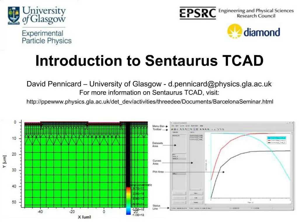
1. Introduction to Sentaurus TCAD
2. Overview Introduction to Sentaurus TCAD software
Building the device structure
Running the simulation
Viewing results
Other software
3. Example simulations � 3D detectors 3D detector � photodiode detector with electrode columns passing through substrate
Small electrode spacing gives fast collection, low Vdep
Radiation hardness
4. Example simulations � 3D detectors
5. Example simulations � 3D detectors
6. Example projects � 3D detectors
7. Basics of simulation The structure of a device is approximated by a �mesh� consisting of a large number of discrete elements
This can be 1D, 2D or 3D
Choice depends on symmetry of device
Differential equations describing the electric potential and carrier distributions are applied to each element
End up with very large number of equations!
Choose boundary conditions for the simulation
E.g. potentials at each electrode
Solve the equations to find the potential and carrier concentrations in each element
Software uses a numerical solver � iterates repeatedly until solution is accurate enough
Mention for simple devices � pn junctionMention for simple devices � pn junction
8. Simulation packages
9. Example of simulation flow
10. Overview Introduction to Sentaurus TCAD software
Building the device structure
Running the simulation
Viewing results
Other software
11. Mesh Mesh takes a �boundary� (.bnd) and command (.cmd) files as arguments:
mesh StripDetector
12. Mesh input files StripDetector.bnd boundary file describes materials & contacts
StripDetector.cmd describes doping profiles and mesh refinement
These are defined first, then placed
Doping:
13. Mesh input files Mesh refinements:
Small elements = more accurate but slower simulation
So, use refinement statements to get smallest spacing in regions with doping profiles, high electric fields, charge generation etc.
3D simulations have more elements, and run far slower, so good mesh design is crucial!
14. Mesh design considerations Boundary conditions
Default boundary conditions are that E and carrier currents perpendicular to boundary are zero
So, boundaries should either be far enough from active region not to have any effect, or along a line of symmetry
Mesh design depends on application � a simple electric field simulation can simply use the smallest repeating region of the device
Mesh for simulating charge sharing in strip detector below: has 2 full electrodes which we use to measure charge sharing, and 2 half-electrodes to approximate the �rest of the device�
15. MDraw Old graphical interface for designing meshes
Can be used in �boundary� and �doping� modes
Materials, contacts, doping and refinement regions can be drawn in
Then, will call on �mesh� to build the mesh
Downsides:
Can�t be used for 3D meshes
Can�t add parameters in Workbench
Can�t be used with NOffset3D (see later)
16. Sentaurus Device Editor New feature of Sentaurus TCAD
Start with sde
Can work in 2D and 3D modes
Has functions for complicated shapes like circles, spheres etc.
In command files or MDraw, these must be built up point-by-point, which is very inconvenient
Has a built-in command line, and can be controlled with scripts
In 3D, easier than using mouse!
Possible to insert parameters using Workbench
17. Sentaurus Device Editor
18. New mesh tool � NOffset3D noffset3d can be run using command files or through Structure Editor, just like mesh
Other mesh tool produce axis aligned meshes
This tool produces unstructured meshes
More effective for creating curved structures
Input command files more complicated � see �Mesh Generation Tools User Guide�
19. Overview Introduction to Sentaurus TCAD software
Building the device structure
Running the simulation
Viewing results
Other software
20. Sentaurus Device Takes mesh, applies semiconductor equations and boundary conditions (in discrete form) and solves
Physics models: Works by modelling electrostatic potential (Poisson�s equation) and carrier continuity
Different versions of physics models available
Different models of mobility, bandgap�
Generation and recombination rates may include avalanche effects, charge generation by high-energy particles�
21. Sentaurus Device � Command file Controlled by a file *_des.cmd
Run with sdevice whatever_des.cmd
File specifies the following:
File - Input and output files
Electrode - List of the device�s contacts
Physics - Physics models used in simulation -
Plot and CurrentPlot - Variables in included in output files
Math - Controls for solver
Solve - Simulation conditions
See example command file
SENTAURUS/Sim folders/Seminar/Workbench/StripDetector_des.cmd
Simulates a strip detector � IV ramp followed by charge collection sim
22. Sentaurus Device � Physics Basic physics models
Mobility � reduced by doping concentration, velocity saturates at high field
Recombination � Shockley-Read-Hall: generation and recombination due to defects in midgap
EffectiveIntrinsicDensity � models narrowing of bandgap at high doping concentration and high temps
Alternative models for parameters such as mobility, recombination etc. are available � see manual
Mobility � reduced by doping concentration, velocity saturates at high field
Recombination � Shockley-Read-Hall: generation and recombination due to defects in midgap
EffectiveIntrinsicDensity � models narrowing of bandgap at high doping concentration and high temps
Mobility � reduced by doping concentration, velocity saturates at high field
Recombination � Shockley-Read-Hall: generation and recombination due to defects in midgap
EffectiveIntrinsicDensity � models narrowing of bandgap at high doping concentration and high temps
23. Heavy Ion
Flexible model for simulating charge generation produced by particle
�Length� is an array. The width of the profile (wt_hi) and the charge generation per unit distance (LET_f) are piecewise-linear
In Math section, use RecBoxIntegr command to improve accuracy of charge generation.
RecBoxIntegr(5e-3 50 5000)
When designing mesh, mesh spacing should be small compared to width of ion track, to ensure accurate generation Sentaurus Device � Useful physics models Mobility � reduced by doping concentration, velocity saturates at high field
Recombination � Shockley-Read-Hall: generation and recombination due to defects in midgap
EffectiveIntrinsicDensity � models narrowing of bandgap at high doping concentration and high temps
Mobility � reduced by doping concentration, velocity saturates at high field
Recombination � Shockley-Read-Hall: generation and recombination due to defects in midgap
EffectiveIntrinsicDensity � models narrowing of bandgap at high doping concentration and high temps
24. Sentaurus Device � Useful physics models Avalanche
Recombination(SRH(DopingDep) Avalanche(Okuto))
Simulates increase in generation from impact ionization
Different models available, aside from Okuto � see manual
In Plot, eAvalancheGeneration and hAvalancheGeneration
If breakdown occurs during an IV ramp, simulation can become very slow: set BreakCriteria in Math section
Oxide charge
Physics models can be specified for particular device regions by inserting a separate physics section:
Oxide charge attracts layer of electrons to interface � need narrower mesh spacing to model this accurately
Oxide charge increases after irradiation
Radiation damage � Talk tomorrow
Mobility � reduced by doping concentration, velocity saturates at high field
Recombination � Shockley-Read-Hall: generation and recombination due to defects in midgap
EffectiveIntrinsicDensity � models narrowing of bandgap at high doping concentration and high temps
Mobility � reduced by doping concentration, velocity saturates at high field
Recombination � Shockley-Read-Hall: generation and recombination due to defects in midgap
EffectiveIntrinsicDensity � models narrowing of bandgap at high doping concentration and high temps
25. .plt files and CurrentPlot Sentaurus uses the word �plot� far too much � don�t get confused!
*.plt files
Contain the electrode potentials and currents throughout the simulation
Can be graphed in Inspect to give IV curves, electrode signals, etc.
CurrentPlot section allows you to add data to these files
Hole density at back surface to test Vdep
Max electric field as a rough guide to breakdown
26. .dat files and Plot *.dat files
Contain variables such as electric potential and carrier concs. at every mesh point in the device
Loaded into Tecplot to show electric field distribution, etc
One .dat file is produced when sim finishes � commands in the Solve section let you produce more
�Plot� section allows you to choose which variables are added
See manual � some physics models have particular Plot variables
27. Math section Controls solving the simulation
Many useful keywords are now default � not really needed in file!
Extrapolate, Derivatives, RelErrControl, NewDiscretization
Can choose numerical solver
�Pardiso� is default, and works well
Solvers user guide lists others
Certain physics models use extra keywords
E.g. RecBoxIntegr improves accuracy of charge generation from HeavyIon or optical generation
Can set break criteria (e.g. to stop simulation if device breaks down)
BreakCriteria {Current(Contact=�pplus1" Absval=1e-6)
28. Solve section Various different processes can be done
Basic solve of Poisson equation, or Poisson Electron Hole
Simply solves device under steady bias conditions applied
Quasistationary
Ramps a parameter (usually bias voltage) from one value to another in series of steps
At each point, device is solved for a �steady state�
E.g. simulating an IV ramp for a photodiode, or response of a transistor
Transient
Simulation over time
E.g. signals produced in a radiation detector when hit by a particle
For both of these, we can control stepping conditions � see file
Smaller step sizes
During the solve, we can produce .dat files (so we can view the state of the simulation at a particular moment)
29. Solve
30. Solve
31. Solve � Iteration tips Sentaurus solves each step by an iterative process
We set a limit to the no of iterations
Success: move on to next step with increased step size
Failure � try again with a smaller step
Generally better to keep number of iterations small (say, 8-10)
More accurate, and frequently quicker, to do small steps with few iterations than large steps with many iterations
�Increment� and �decrement� control changes in step size
Default increment is 2 (double step size after success). If sim starts fine, but we get repeated failure later on, useful to reduce Increment
des.log files record output
Typing dessisstat whatever.log will look through a log file and summarise the information
32. Mixed mode simulation In standard simulation, we have a single device with boundary conditions
Mixed mode simulates one or more devices, plus extra components such as resistors, voltage sources etc., modelled by Spice
See Compact Models User guide for details of components
E.g. can have AC-coupled detector with strips biased through resistors
Can do transient simulations with time-varying voltage sources
E.g switching behaviour of a transistor
CCD simulation � use HeavyIon to generate charge within one pixel, then a time-varying voltage to transfer charge to next pixel
Mixed-mode is needed to do C-V simulation
�ACCoupled� command
Main difference � Sentaurus file has to describe all the devices present, and how they are connected
See StripDetector_CV_des.cmd
Sentaurus Device manual also has examples
33. Mixed mode simulation file
34. Mixed mode simulation file
35. Mixed mode � typical CV commands
36. Overview Introduction to Sentaurus TCAD software
Building the device structure
Running the simulation
Viewing results
Other software
37. Inspect Creates graphs from *.plt files created by Sentaurus Device
Contains electrode voltages, currents etc, and �time�
Contains data produced by CurrentPlot (e.g. max electric field)
Can graph any pair of data sets
38. Inspect After creating a curve, can use File->Export->XGraph to export a file with x,y data points
Can then be used in other programs like Origin
Can do mathematics on graphs using �new� button
integr(<currentgraph>) to integrate a current pulse over time
Scripting language is available to control Inspect
*ins.cmd script file can be loaded
See Inspect manual for language
Scripts->Record allows you to carry out a series of steps by hand, and writes the corresponding commands to a file
Scripting language allows you to extract data from projects when using Workbench
39. Tecplot SV Can load *.grd and *.dat files
View meshes
View field distributions etc produced by Sentaurus device
Contour plots, vectors�
tecplot_sv command
Tecplot is a general-purpose package for viewing 2D and 3D plots
http://www.tecplot.com
Synopsys then added on extra functions
Manuals
Tecplot SV user guide only describes extra functions (58 pages)
Tecplot User Manual describes regular version of package (632 pages)
Tecplot Reference Manual gives script commands (320 pages)
40. Tecplot SV Two different sidebars are available: Synopsys and Tecplot
Switch using the View menu at the top
Synopsys sidebar - useful basic commands
Basic commands for loading files, zooming, inserting text/lines etc
List of variables to plot, and ranges to set
Can also add legend etc
Menu to choose which material we apply commands to
Options to make the following visible/invisible
Mesh structure
Boundary
Vector plots (for quantities like E-field)
Contour lines, flood
(On right) options to make 2D cuts from 3D device simulations
(On right) display or hide p-n junctions and depletion regions
41. Tecplot SV Tecplot Sidebar
Option to switch between 2D and 3D!
�Zone style� gives lots of options for controlling contours, vectors etc.
Better tools for:
Controlling contour lines and streamtraces
Moving and rotating 3D objects
Menus at top of screen � many, many options!
Same features as sidebars, but often more control
E.g. taking 2D slices at unusual angles
Saving states and images
Saving a �layout� file saves state of simulation
Saving a �style� file just saves formatting � can load another data set then the style file to apply formatting
Recording and using macros
Creating new variables using existing ones
E.g can find the components of a vector in a particular plane
42. Overview Introduction to Sentaurus TCAD software
Building the device structure
Running the simulation
Viewing results
Other software
43. Simulation packages
44. Sentaurus Process Process simulation
Can be controlled interactively (series of commands) or with command file
Simple case � 1D simulation
Start with, say, a doping implant
Describe a series of processing steps (time, temp)
Simulation finds the 1D doping profile after the stages
Produces a .plx doping file, which can then be used in mesh
2D and 3D simulation
Once again, need to describe a series of processes (implants, annealing, etc.)
In this case, also have to define masks used
Also, simulation is carried out on a grid of points � similar considerations to refinements in mesh design
Finally, automatically produces input files for mesh
45. Ligament Graphical interface to produce command files for Process
Flow editor � create a list of process steps
Ligament layout editor � MDraw-like package for defining �masks� used for each process step
46. Sentaurus Workbench Project control tool
Allows you to repeatedly run multi-stage simulations using different parameters each time
This includes producing graphs of results or extracting data like CCE
Tutorial next!
47. Other information This is part of a Sentaurus TCAD seminar:
http://ppewww.physics.gla.ac.uk/det_dev/activities/threedee/Documents/BarcelonaSeminar.html
The page includes a .tgz file with the simulation files referred to in this talk
Basic strip detector simulation � folder SENTAURUS/Seminar/Introduction
StripDetector.bnd/cmd files for mesh
StripDetector_des.cmd file for Sentaurus Device
The simulation has already been run, and output files are in the same folder
CV simulation
Uses the same mesh as before
StripDetector_CV_des.cmd
Synopsys website �
https://solvnet.synopsys.com/amserver/UI/Login
Can sign up to get a login ID. Can get all the manuals, plus some simulation examples
Sentaurus Device simulation examples
$STROOT/tcad/$STRELEASE/lib/sdevice/GettingStarted
Files corresponding to examples in SDevice manual