Download
1 / 38
650 likes | 1.48k Views
Early experiments with electricity. Benjamin Franklin was a scientist in the 18 th century. He carried out many experiments with electricity, including this one. Franklin proved the link between lightning and electricity using a kite attached to a metal key. Don’t try this at home!.

E N D
Early experiments with electricity Benjamin Franklin was a scientist in the 18th century. He carried out many experiments with electricity, including this one. Franklin proved the link between lightning and electricity using a kite attached to a metal key. Don’t try this at home!
What is an electrical circuit? • An electrical circuit is like a central heating system: • There is a pump that pushes water around the system. • The water everywhere starts to move at the same time. • There are pipes that carry the water. • The water flows through the pipes.
Drawing electrical circuits Scientists don’t draw circuits as they look in real life. This is because it takes too long and each person would draw something slightly different. Instead, they use circuit symbols to represent each component in the circuit. They are drawn exactly the same way each time! Wires are drawn as straight lines. They don’t have to represent the real lengths of the wires.
What is a series circuit? This is a simpleseriescircuit. In a simple series circuit, everything isconnected in one loopacross the terminals of the battery. There are no points where the current can split or join (these are called junctions). This circuit has two lamps connected in series. Circuits are always drawn using straight lines.
Examples of series circuits Here are some other simple series circuits: • Two resistors connected in series. • A variable resistor (or rheostat) and a bulb connected in series.
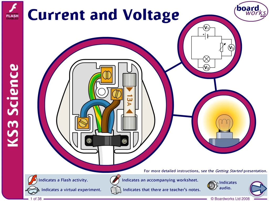
Measuring current The unit of measurement forcurrentis the amp, which has the symbol A. Current is measured using a device called anammeter. In a circuit diagram, an ammeter is shown by an ‘A’ in a circle. When measuring the current through a component, the ammeter is always connected inseries(in the same loop) with that component.
Measuring voltage Voltage is measured using a device called a voltmeter. In a circuit diagram, a voltmeter is given the symbol V. When measuring the voltage across a component, the voltmeter is always connected inparallelwith (or across) the component. This is still a series circuit, as the voltmeter does not affect the circuit. The voltage supplied by the battery is shared between all the components in a series circuit.
Series circuits – key ideas • In aseries circuitthe current is thesamein all parts of the circuit. Series circuits are found in torches and strings of Christmas lights. • The supply voltage issharedbetween the components in a series circuit. (The sum of the voltage across each component is the same as the total supply voltage.) • The current depends on the voltage in any circuit.
What is a parallel circuit? A B A parallel circuit is one that contains a point (a junction) where the current can split (point A) or join (point B). This means that there is more than one path around the circuit.
Measuring current in a parallel circuit Ammeter Current (A) A1 A2 A3 A4 Set up the circuit as shown. Place an ammeter, in turn, at positions 1, 2, 3 and 4 and record the readings in a table.
Current in a parallel circuit In a parallel circuit, the current that leaves the cell is the same as the current that returns to the cell. The ammeter readings for A1 and A4 should be the same. This is because the current does not get used up by the circuit, just the energy that the current is carrying.
Current in a parallel circuit The current splits up at the first junction and then joins together at the second junction. The following is always true for this type of parallel circuit: A1 = (A2 + A3) = A4 If the bulbs are identical, then the current will split evenly. If the bulbs are not identical, then the current will not split evenly.
Measuring voltage in a parallel circuit Voltmeter Voltage (V) V1 V2 V3 Connect up this circuit and measure, in turn, the voltage at V1, V2 and V3. Record your results in the table. What do you notice about the results? How can you explain this?