Download
1 / 23
280 likes | 767 Views
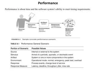
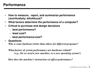
Performance Performance is the study of how high, how fast, how far, and how long an aircraft can fly. It is one part of the general study of flight dynamics which also include stability and control – however, performance estimates are often made by aerodynamicists.

E N D
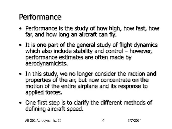
Performance • Performance is the study of how high, how fast, how far, and how long an aircraft can fly. • It is one part of the general study of flight dynamics which also include stability and control – however, performance estimates are often made by aerodynamicists. • In this study, we no longer consider the motion and properties of the air, but now concentrate on the motion of the entire airplane and its response to applied forces. • One first step is to clarify the different methods of defining aircraft speed. AE 302 Aerodynamics II
p0 p p0 p V V Airspeed Measurement • The Pitot-Static system is the standard device for airspeed measurement • At low speeds, this system makes use of Bernoulli’s equation to obtain V from pressures and density AE 302 Aerodynamics II
Airspeed Measurement (continued) • To measure the aircraft’s True Airspeed, TAS, at incompressible velocities: • However, there is no simple device for measuring density. Thus, airplane instruments are calibrated assuming sea level density, rs. • The resulting velocity is called the Equivalent Airspeed, EAS, AE 302 Aerodynamics II
Airspeed Measurement (continued) • Notice that EAS and TAS are related by the density ratio, s, • In fact, EAS is more useful to pilots since equivalent stall speed, Ve stall, is independent of altitude while true stall speed, Vtrue stall, is not!! • This is because aerodynamic forces are proportional to dynamic pressure not velocity. At the same Ve you have the same q, at any altitude! AE 302 Aerodynamics II
Airspeed Measurement (continued) • At subsonic compressible velocities, the true airspeed can be calculated from the isentropic Mach relation (which we will derive later): • From this, the true velocity can be found from: • The terms were rearranged since a Pitot-static system measure pressure differences! AE 302 Aerodynamics II
Airspeed Measurement (continued) • In application, aircraft instruments are calibrated assuming sea level air density and pressure, s and ps. Thus, the Calibrated Airspeed, CAS, is: • Believe it or not, this relation reduces to our EAS relation at low velocities, or really low Mach numbers. • Thus CAS also has the benefit of providing a stall speed which is independent of altitude. AE 302 Aerodynamics II
Airspeed Measurement (continued) • The book notes that the main difference between calibrated and equivalent airspeeds is the assumption of constant density. • As a result, equivalent airspeed at compressible speeds may be calculated by: • The factor which relates Vc and Ve is given the symbol f, but it is a bit long expression – see the book for the equation and tables for it value. Ve = f Vc AE 302 Aerodynamics II
Airspeed Measurement (continued) • It has been assumed thus far that the Pitot-static system correctly reads both the total and static pressure and that the instrument displays the right value to the pilot. • In practice, this is not always true. As a result, even after calibration, there may be sensor position errors in the measure airspeed. • Thus, the Indicated Airspeed, IAS, which is displayed on the cockpit instrument may differ from both EAS and CAS. • DVp is the position errors of the system. AE 302 Aerodynamics II
t c i e Airspeed Measurement (continued) • Thus, the process of going from the airspeed a pilot sees to the true air speed is: • Convert indicated to calibrated: • Convert calibrated to equivalent: • Convert equivalent to true: • Because of the sequence of steps and the relative magnitudes of the results, the mnemonic ice-t along with a square root radical is used. AE 302 Aerodynamics II
Airspeed Measurement (continued) • Two final, but important, notes: • First is that the aviation business still uses knots as the standard unit of airspeed – not ft/sec or m/sec. • Thus, airspeeds are usually given as KIAS, KCAS, KEAS or KTAS on instruments and in flight manuals. • And last, the air we fly in is usually not at rest. Thus, Ground Speed of an aircraft is obtained from the vector sum of the airspeed and wind velocities: Vt Vwind Vground AE 302 Aerodynamics II
Performance (continued) L • Note the new vector angles: • Flight path angle, g : the angle between the velocity vector of the aircraft and the horizon. • Thrust line angle, fT: the angle between the aircraft reference line and the action line of the powerplant. T, Thrust line g fT aircraft reference line a V, Flight path g Horizon D W AE 302 Aerodynamics II
Performance (continued) • In your aerodynamics courses you learn how to accurately calculate the lift and drag of aircraft. • However, in performance, we just need quick estimate, primarily for how drag depends upon lift. For this we use: • The zero lift drag, CD,0, is due to viscous effects over the entire airplane surface - wing, fuselage, etc. when CL=0. • The second term includes both the span efficiency of the wing and any variation in viscous drag due to lift. AE 302 Aerodynamics II
Equations of Motion • An airplane in flight obeys Newton’s Laws of motion. In particular: force = mass * acceleration. • For airplanes, we split the forces in to those in the flight direction and those perpendicular to it: • Note that in the perpendicular equation we allow for a curved flight path with radius rc. • Summing forces gives: AE 302 Aerodynamics II
Equations of Motion (continue) • The previous equations are the general equations of motion for an airplane. They are applicable to all flight conditions. • A tremendous simplification occurs if we limit the study to steady, level, unaccelerated flight (SLUF). dV/dt = 0 rc = 0 • Also, in most airplanes, the thrust angle is small enough to assume cos(T+)~1 and sin(T+)~0. • Under these assumptions, AE 302 Aerodynamics II
Thrust Required • The thrust acting on an airplane should be considered from two different viewpoints: • The thrust required by the airplane to stay in flight at the existing flight conditions, I.e. V, h, g, etc. • The thrust available from the powerplant to maintain or change those flight conditions. • Lets start with the thrust required. From the previous relations: • Or, since Steady, Level, Unaccelerated Flight AE 302 Aerodynamics II
Thrust Required (continued) • The second relation points out a very important point: the minimum thrust require occurs when the airplane lift to drag ratio, L/D = CL/CD, is maximum. • The first equation is more useful however in finding when this occurs. Substituting our previous relation for drag yields: Drag due to lift (Induced drag) Profile or Parasitic Drag AE 302 Aerodynamics II
Thrust Required (continued) • This equation assumes that L=W as is appropriate for SLUF. • However, we can include accelerated flight by simply including a load factor, n, term: L = nW. • In this case: • Where the dynamic pressure term has been expanded, and the symbol K is used to represent: AE 302 Aerodynamics II
D, TR Total drag, Require Thrust, TR Parasitic drag Induced drag V V for min D and TR, and max L/D Thrust Required (continued) • Note how the two contributions to drag vary differently with velocity: AE 302 Aerodynamics II
Thrust Required (continued) • From this we see that a minimum in required thrust occurs at some value of velocity (or, similarly, q). • To find this minimum, we differentiate this relation with respect to q and set the derivative to zero: • Thus, the minimum drag occurs when the parasitic drag and drag due to lift are equal! AE 302 Aerodynamics II
CL (L/D)max CL,L/D max CL/CD = L/D CD,0 2CD,0 Thrust Required (continued) • This effect can also be seen by looking at a parabolic drag polar • Any line from the origin has a slope equal to the L/D ratio. • Thus, the maximum L/D occurs at the tangency point shown. CD AE 302 Aerodynamics II
TA Turbojet Piston-Propeller M 1.0 Thrust Available • Thrust available is a function of the power plant type/size and aircraft velocity and altitude. • Typical thrust available variation with velocity is shown here for two engine types: • For piston-propeller combinations, thrust decreases at high speed due to Mach effects on the propeller tip. AE 302 Aerodynamics II
Thrust Available • For turbojet engines, thrust normally increases slightly with speed due to the increased inlet performance and increased mass flow rate with Mach number. • Other engine types like turboprops and turbofans have thrust variations somewhere between these two. • The best source for engine performance data is the manufacturer themselves provided in the form of an “engine deck”. • Also realize that engine thrust also depends upon the throttle setting. AE 302 Aerodynamics II
T Piston-Propellor TA Sonic Speed TR V,max V,min V Thrust Available (continued) • For a given airplane, the range of possible steady flight velocities depends upon the relative values of thrust required and thrust available: • Steady level, un-accelerated flight is only possible when TA TR. • To fly at velocities between V,min and V,max, the throttle setting would be set less that 100%. AE 302 Aerodynamics II