Download
1 / 25
250 likes | 521 Views
Technical drawings graphically communicates a description of the part to be

E N D
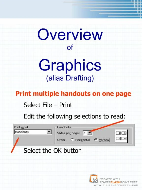
1. Overview
of
Graphics
(alias Drafting)
2. Importance of Graphics Technical drawings graphically communicates a description of the part to be �manufactured� between the engineer and manufacturing/ marketing/ analytical group.
Also, it provides a vehicle for one�s thoughts to be visualized by another person
Universal language
3. Drafting Standards Standards organizations like ANSI (American National Standards Institute) and ISO (International Standards Organization) publish standards detailing how drawings should be created so they can be interpreted universally.
To eliminate confusion, American National Standards Institute (ANSI) called on American Society for Engineering Education (ASEE), Society of Automotive Engineers (SAE), and American Society of Mechanical Engineers (ASME). Together they prepared American National Standard Drafting Manual Y14 (ANSI Y14). http://www.ansi.org
4. Design & Graphic Communication Types of Drawings
Artistic & Technical
What is a Technical Drawing
Technical
related to scientific, industrial, or mechanical
Drawing
a graphic representation of an object, an idea, or a proposed design
Technical Drawing
a graphic representation of an object, an idea, or a proposed design that is scientific, industrial, electrical, or mechanical.
Engineering Design Graphics
technical drawings representing designs & specifications for physical objects
5. Objectives in Drafting Legibility
must be able to read and interpret
Accuracy
valid and convey proper size or shape
Neatness
no smudges, rips, etc...
Speed
time is money
6. Types of Communication Sketching � still used, especially when designing a product
Board drawing � phasing out
CAD
Computer-Aided-Design or Computer-Aided-Drafting
CADD
Computer-Aided-Design and Drafting
7. A set of working drawings must:
Describe the parts � visually and dimensionally.
Show the parts assembled.
Identify all parts.
Specify standard parts.
A set of working drawings contains the following items:
Assembly drawing
Detail drawings
Parts list
Specifications Goal: Working Drawings
8. Shape Description 3-dimensional (3D)
2-dimensional (2D)
9. 3-Dimensional (METBD 110)
10. 2-Dimensional (METBD 110)
11. Most Common Views
12. Size Description Dimensions
Notes
13. Dimensions (METBD 110)
14. Notes (METBD 110) Written specifications: I.e.,
Note: All fillets and rounds are R.13, unless otherwise specified.
Note: Material 1/8 thick.
15. Solid Modeling (METBD 110) Pro/ENGINEER rest of semester
16. Additional Topics
17. Section View (METBD 110 & 111)
18. Auxiliary Views (METBD 110 & 111)
19. Assembly (METBD 111)
20. Tolerancing (METBD 111) Maximum and minimum dimension may be
21. GD & T (METBD 111) States maximum variation allowed.
22. Fasteners (METBD 111) External thread
I.e., broom handle, top of a plastic pop bottle, bolt
Internal thread
I.e., lid for plastic pop bottle, nut
23. Thread Information (METBD 111) External thread
Internal thread
24. You are now ready for METBD 306/307 Computer-Aided-Design
25. Let�s Step Back Look at the METBD 110 Big Picture
How does this course fit into engineering?