Download
1 / 42
430 likes | 1.3k Views
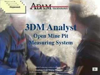
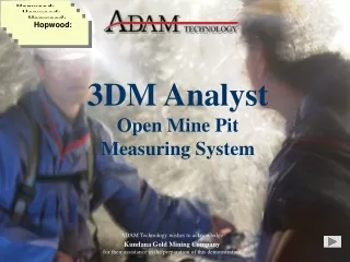
Using 3DM Analyst Mine Mapping Suite for Rock Face Characterisation. Jason Birch, Managing Director ADAM Technology sales@adamtech.com.au http://www.adamtech.com.au. Copyright © 2006 ADAM Technology. Session Overview. Company Background Principals of Photogrammetry

E N D
Using 3DM AnalystMine Mapping Suite for Rock Face Characterisation Jason Birch, Managing DirectorADAM Technology sales@adamtech.com.au http://www.adamtech.com.au Copyright © 2006 ADAM Technology
Session Overview • Company Background • Principals of Photogrammetry • 3DM Analyst Mine Mapping Suite • Components • General Workflow • Key Features • Image Capturing Methods • Applications • Common Problems • Q&A
Company Background • 20 years’ experience in the photogrammetric industry (founded in 1986) • Designed, manufactured, and sold hundreds of analytical stereoplotters worldwide, including many MPS-2s to mining companies • Embarked on what was to become the 3DM technology(3-dimensional, Dynamic Measurement) in 1996 • Developed and installed many custom photogrammetric factory control systems in Japan for glass bottle making (3DM Gob) and rubbish pit control (3DM Bunker) • Wholly Australian-owned private company — all research, development, and manufacturing conducted in Perth, Western Australia
Principals of Photogrammetry Photogrammetry is the science of using 2D images to make accurate measurements in 3D. To do that, the information that was lost when the image was captured needs to be recovered. The location of any point in an image can be described with just two co-ordinates: (x,y). Images are only two-dimensional. The location of any point in the real world can be described by three co-ordinates: (x,y,z), (latitude, longitude, altitude), etc. The real world is three-dimensional.
Perspective Centre Focal Length Image Sensor Possible points of origin Top-down view Principals of Photogrammetry Problem: The light that hits a given pixel in the image could have come from any point along the ray from the pixel, through the perspective centre, into the scene.
Image Sensor Unique 3D location! Top-down view Principals of Photogrammetry Solution: Adding another image taken from a different location allows us to intersect the rays and determine the 3D location of the point where the light came from!
ExteriorOrientation Image Matching Principals of Photogrammetry Information needed to determine 3D locations: • The location of each camera’s perspective centre. • The orientation (rotation) of each camera about its perspective centre. • The location of the point on each image sensor. This is the essence of photogrammetry!
Determining Exterior Orientations Absolute orientation: • All data is registered in a real-world co-ordinate system using known points (control points and/or camera stations) • At least three known points required in project (regardless of how many images are used) Relative orientation: • Data is registered in an arbitrary co-ordinate system (can be specified) • Scale normally provided by known separation(s) between camera positions and/or known distances between points in scene • All images in project must be “connected”
Determining Exterior Orientations Inputs: • Image co-ordinates of all control points and relative-only points • Image co-ordinate sigmas (Sx,Sy) • Control point co-ordinates • Camera station co-ordinates • Individual co-ordinate sigmas for both control points and camera stations (Sx,Sy,Sz) Outputs: • Adjusted image co-ordinates for all points • Adjusted control point co-ordinates • Exterior orientations • Derived ground co-ordinates for all of the relative-only points
Focal Length Focal Length Image Image Important Characteristics of Photogrammetry • Relatively range-invariant — simply choose the lens required to obtain the desired ground pixel size: Object
Important Characteristics of Photogrammetry • Accuracy highly configurable — planimetric accuracy depends on image accuracy and ground pixel size; depth accuracy additionally depends on camera separation: Good values for : • 0.5: Conservative value for planning • 0.3: Reasonable estimator of actual accuracy in most cases • 0.05: Best value actually observed (circular targets)
Visualising Accuracy • The relationship between accuracy in the image, planimetric accuracy, depth accuracy, and base:distance ratio can be visualised by looking at the “error ellipse” that is formed when we adjust the location of the point in each image by the image accuracy: Error Ellipse
Visualising Accuracy • Increasing the base relative to the distance makes the error ellipse more circular, improving the depth accuracy: Error Ellipse
Measured Accuracy BHPB Iron Ore, Mt Newman: • Application: Geotechnical analysis • Typical working range: 700m to 1.2km • Nominal ground pixel size: 4cm × 4cm • Typical accuracy: 0.1m to 0.2m
Measured Accuracy BMA Coal, Queensland: • Applications: Surveying, resource modelling, geotechnical analysis • Typical working range: 50m • Typical ground pixel size: 1.5cm × 1.5cm • Typical accuracy: 0.01m to 0.02m
Measured Accuracy Fugro Spatial Solutions, Western Australia: • Application: Measuring road subsidence while train tunnel being constructed underneath it • Working range: 20m • Ground pixel size: 0.5cm × 0.5cm • Accuracy: 0.0004m! (Surveying retro-reflective targets)
Measured Accuracy How is it measured? • Most comprehensive: Manually measure control points in 3D images, compare with surveyed locations • Easiest: Read bundle adjustment report to see residuals • Good practice: Withhold some control points to act as “check points” — residuals should be the same as the control points actually used • Caveat: Need redundancy for this to work! Only three known locations data will fit perfectly and residuals will be 0! Problem: Reported accuracy will never be better than the actual accuracy of the survey data!
3DM Analyst Mine Mapping Suite Digital photogrammetric system designed to work with modern digital cameras: • Automatically determines relationships between camera positions (relative orientation) simply by inspecting images • Automatically generates 3D surface data from imagery • Powerful vector data digitising and editingtools withover 160,000 user-definedfeature typessupported • Extensive operator assistance whenever human input is required • Built-in digital camera calibration routines
3DM Analyst Mine Mapping Suite • 3DM CalibCam • Performing camera calibrations (interior orientations) • Determining exterior orientations (camera positions and directions) for any number of images simultaneously • Surveying targets accurately (up to 80,000:1!) • Creating extremely high-resolution merged images • 3DM Analyst • Generating, editing, and merging DTMs • Digitising vector data using Single Image mode, Stereo, or 3D mode • Analysing data — volume calculations, face detection, etc. • Exporting data as 3D Images, DXF, etc. • DTM Generator • Generating DTMs and resulting 3D Images in batch mode
Workflow Geotechnical analysis in VULCAN: Capture Images 3DM CalibCamor 3DM Analyst Determine camera orientations 3DM Analyst orDTM Generator Generate DTMs & 3D Images Import 3D Images into VULCAN for interpretation VULCAN
Workflow Other applications: Capture Images 3DM CalibCamor 3DM Analyst Determine camera orientations 3DM Analyst orDTM Generator Generate DTMs Analyse data: calculate volumes, digitise vector data, etc. 3DM Analyst
Key Features • Ease of use • Works with any digital camera • Workflow is extremely automated and robust • Intelligent troubleshooting built-in • Accuracy • Speed • 15 seconds to automatically determine camera orientations;five minutes to generate 250,000 DTM points on a 2GHz PC • Flexibility • Works with images captured in any environment under almost any circumstances • Can be used for almost any task where accurate 3D data is required
Ease of Use Demo The only thing not automated is determining the location of the data in the physical world!
Flexibility — Image Capturing, etc. • Images can be captured in any configuration (convergent; strips; fans), even in the same project • No pre-requisites on camera orientations —software will work that out automatically! • Any control data supplied in any configurationand with any accuracy will be used in thesolution • Camera calibration can be performed on an ad-hoc basis if required using the same imagery as captured for the project and it can be analysed to ensure validity
Optional overlap between models Image Capturing: Independent Models Pros: • Conceptual simplicity • Flexibility — depth accuracy can be freely adjusted by changing base, can be used with lenses of any focal length over any distance Cons: • Each model needs to be fully controlled (at least three known locations — control points and (optionally) camera stations) • Extremely vulnerable to bad control due to low level of redundancy
Image Capturing: Image Strips • Series of parallel images overlapping neighbours by at least 50%. (May be arranged in multiple rows, overlapping about 10%.) Pros: • Gives accurateexterior orientations with very few control points —one control point for every five images is generally more than adequate • Ideal for aerial imagery Cons: • Base is determined by field of view, which is determined by focal length — best with short focal lengths
Second model First model Image Capturing: Image Fans • Series of images overlapping neighbours by about 10% captured from each camera station Pros: • Fewer unknowns give strong orientations with very few control points — minimum is one control point plus two camera stations for entire project! • Very fast — rotating camera to capture next area much quicker than relocating camera • Images can be merged (and treated as independent models in 3DM Analyst) allowing very high resolution images with cheap cameras
Applications — Geotechnical Analysis BHPB Diamonds Ekati Koala mine: • Camera: Nikon 1Ds, 135mm lens • Project area: 500m × 300m • Number of images: 27 from each camera station • Number of camera stations: 2 • Distance to pit wall: 700m • Ground coverage: 120m × 80m per image (3cm pixel size) • Number of control points: 7 (placed around the top of the pit in safe locations) • Accuracy: Sx = 0.14m, Sy = 0.08m, Sz = 0.04m. • Processing time to generate 3D images from scratch: 4 hours, only 8 minutes of which was actual user time!
Applications — Geotechnical Analysis Key advantages: • Data can be obtained remotely when there is no safe access (up to 3km away!) • Features can be identified that would not be apparent at close range • Speed of acquiring data compared to other methods • Accuracy and detail of data compared to other methods • Acquiring the data has little impact on other activities • Images form a permanent record that can be referred back to in the future • The physical components — the parts that can break down — are relatively cheap, available from many suppliers, and easy to replace
Applications — Aerial Mapping Thiess Indonesia: • Camera: Canon EOS 300D, 28mm lens • Project area: 140km (captured in one day) • Number of images: ~1,200 • Flying height: 600m – 800m • Ground coverage: 600m × 400m per image (20cm groundpixel size) • Accuracy: 0.2m
Other Applications Tunnel Mapping Resource Modelling Truck Volume Calculation
Exciting New Developments Cost-effective aerial photography using fully autonomous UAVs: • Ideal for pit mapping and stockpile volume calculations • 2 hour endurance, 100 hour service interval, 6,000 feet ceiling • Onboard GPS for autonomous navigation —program in desired camera locations as waypoints,UAV captures images from each waypoint in turn
Common Problems Bad imagery: • Poor quality images — blurry, badly exposed, optically different from calibration use prime lenses, tripod, aperture priority (f/8), focus at infinity (or use autofocus at distances similar to calibrated distance) • Incomplete coverage of area being mapped plan better, capture redundant images (images are cheap!), go back and capture additional images if possible Bad observations: • Bad control point/camera station co-ordinates plan for redundancy so bad points can be disabled • Incorrect observations of points in the images correct them! • Insufficient relative-only points reduce matching tolerance, use a lower ISO setting to reduce noise, digitise one or more “seed” points manually
Common Problems Bad DTMs: • Large number of bad points increase matching tolerance, use automated spike removal tools, use a lower ISO setting on the camera to reduce noise • Incomplete/sparse DTMs reduce matching tolerance, use a smaller base, use a lower ISO setting on the camera to reduce noise, digitise data manually as a last resort
3DM Analyst Lite • Designed for customers with less demanding workloads: • Can calculate exterior orientations for two images at a time • Supports images of up to 16 megapixels • Can upgrade to any other product in the range at any time simply by paying the difference in list price for the software and support agreement • ADAM Price Guarantee: List prices for upgrades are fixed as long as your ADAMcare support agreement is continuously maintained
3DM Analyst Lite Suite • Combines 3DM Analyst Lite and 3DM CalibCam Lite • Designed for customers with larger workloads and who want to reduce the number of control points required for absolute orientations: • Can calculate exterior orientations for up to 10 images at a time • Supports images of up to 24 megapixels • Supports image merging allowing cheaper cameras to be used to generate high-resolution images
3DM Analyst Mine Mapping Suite • Combines 3DM Analyst, 3DM CalibCam, and DTM Generator • Designed for customers with very large workloads and who want to be able to calibrate their own cameras: • Can calculate exterior orientations for any number of images at a time • Supports images of up to 65 megapixels (on a PC with 2GB of RAM) • Supports image merging • Supports camera calibration • Supports batch processing of any number of DTMs offline (+ generate 3D Images from them) without human intervention • Separate dongles for 3DM Analyst and 3DM CalibCam so both can be used simultaneously on separate PCs
3DM Analyst Professional • Designed for professional mapping organisations working with large format scanned images: • Can process any number of images at a time • Supports images in excess of 250 megapixels • Supports batch processing of any number of DTMs offline (+ generate 3D Images from them) without human intervention