Download
1 / 50
510 likes | 723 Views
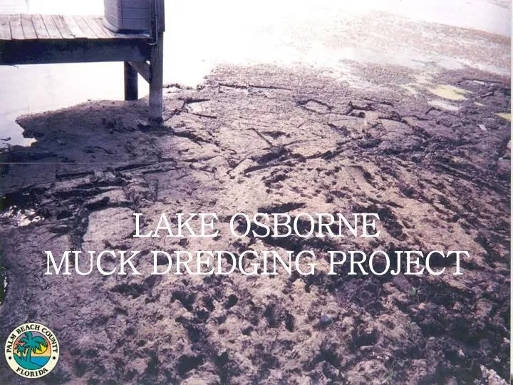
LAKE OSBORNE MUCK DREDGING PROJECT. Presentation Overview. What are the Chain of Lakes? How have the lakes become degraded? Palm Beach County’s Involvement - State of the Lakes Plan What is Muck? - How does muck develop? How much muck is in the lake and how do we know? - Surveys

E N D
PresentationOverview • What are the Chain of Lakes? • How have the lakes become degraded? • Palm Beach County’s Involvement - State of the Lakes Plan • What is Muck? • - How does muck develop? • How much muck is in the lake and how do we know? - Surveys • What is the County’s plan? - Lake Osborne Muck Dredging Project • Lake Osborne Muck Dredging Project • Brennan Marine Professionals • Dredging Equipment • Dewatering Plant • Drying Methods • Disposal of Muck • Future of the Project
CHAIN OF LAKES • Part of a natural lake system that, at one time, extended from West Palm Beach to Delray Beach • The E4 canal connects Pine Lake, Lake Clark, Lake Osborne, Lake Eden, Lake Ida • Freshwater lakes: • provide habitat for native flora & fauna • replenish drinking water supplies • store and filter storm water • provide recreational opportunities • aesthetically appealing
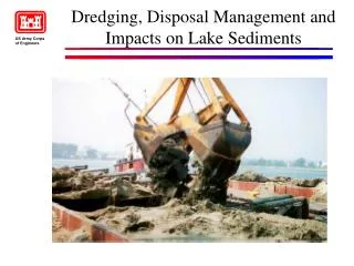
Degradation of a System Historical dredge & fill activities, urban encroachment & discharge from canals.....
South Lobe of Lake Osborne (1986) ...lead to the lakes’ waters becoming overloaded with nutrient-rich organics
As a result, excessive plant life (algal blooms) develops throughout the Chain of Lakes causing a decrease in water quality & reduction in oxygen levels HYDRILLA
STATE OF THE LAKES PLANThe lakes’ decreasing quality prompts Palm Beach County’s Department of Environmental Resources Management to commission a report in 1997 to address how to enhance and improve the freshwater system and its managementThe plan focuses on the following goals: • Restore and Protect Wetland Habitats • Protect & Improve Water Quality • Control Exotic Vegetation • Maintain & Enhance Fisheries • Enhance Public Participation & Environmental Awareness
MUCK What is MUCK? Muck is organic and inorganic sediments, sands, silt, debris and other materials How does MUCK form? Muck is a result of the excess nutrients in the water. Excess nutrients are attributed to: -Lakes’ extensive development -Herbiciding of non-native vegetation -Discharge of several canals How long has MUCK been accumulating throughout the lakes? -50 plus years
In 2002, the County contracts with the survey company, Morgan & Eklund, INC., to measure the amount of muck throughout Lake Osborne Method of Measurement:dual frequency transducer• Transducer captures the top of the muck layer and natural sandy lake bottom to determine muck’s thickness
LAKE OSBORNE MUCK DREDGING PROJECT • Surveys reveal 700,000 CY of muck cover the sandy lake bottom • In response, Palm Beach County develops the Lake Osborne Muck Dredging Project County divides the dredging of the southern lobe into phases: Phase I: removal of approximately 20,000 cubic yards of muck, in situ, from a 199,241 square foot section Phase II: removal of approximately 85,000 cubic yards of muck, in situ from a 1,015,010 square foot section
LAKE OSBORNE MUCK DREDGING PROJECT • County decides to pay selected contractor by the square footage vs. cubic yard because of the consistency of the material • Muck is difficult to measure volumetrically because there is no defined top layer • 1.2 million square feet (approximately 28 acres) throughout the project site • $1.12 per square foot • Total project cost for Phase I & II: 1.4 million dollars
County awardsBrennan Marine Professionals Phase I of the contract in March 2004 • Brennan receives Phase II of the project if they are able to meet project deliverables & complete work within allotted time frame for Phase I • Project Time Frames: Phase I - 45 days from Notice to Proceed to mobilize all equipment (no payment for mobilization) 70 calendar days after mobilization to complete dredging and dewatering of material from Phase I Phase II – 300 calendar days from issuance of the second Notice To Proceed to complete Phase II
Spring 2004: Brennan receives Notice to Proceed in March and begins to mobilize equipment in April Mobilization at Melear Park: April 22, 2004
Fusing & placement of polyethylene plastic pipe Mobilization: April 22, 2004
Eight (8) inch intake pipeline transports muck (slurry) to the dewatering plant
Buoys & signage along the pipelines warn recreational users of the pipes’ presence
8” Swinging Ladder Rotating Cutter Head Suction Dredge - 3 Spud System - Hydraulically Actuated Spud Frame enables dredge to walk along the lake bed DredgingEquipment
Interface between the dredge operator & field conditions Dredge Operator Booth
RTK Global Positioning System RTK Positioning System provides sub-centimeter accuracy for position of dredge and cutter head DREDGEPACK Software Uses county surveys that designate dredge depths Screen displays operator position & amount of material being removed Tracks & recalculates the amount of material to be excavated Displays new calculations on the screen until achieving designated dredge depth High Tech Instrumentation on the Dredge Includes:
Pay Survey Deliverable Dredge Track Lines: demonstrate where the dredge’s cutter head is working throughout the day
Wheel removes sand from slurry Contains 200-mesh (.074 mm) screens
SCALPER Removes debris & organics by gravity feeding slurry through a belt screen FRAC TANK Slurry homogenizes in frac tank (Only minus 200-mesh /.074 mm solids remain)
VIBRATORY SCREEN • Material travels over a 5’ x 7’ vibrating screen (35-mesh/0.5 mm) • Vibration causes the sands & larger material to move toward the discharge end of the screen where it is placed on the radial stacker • Material finer than 35-mesh/0.5 mm drops through the screen into a sump
Slurry collecting in sump is pumped and delivered to two cyclonic separators The cyclonic separators perform like a centrifuge, using 320-mesh screens to further separate the slurry Finer material spins out the top of the separators & moves toward the frac tank HYDROCYCLONES(now in use) • Larger material falls to the bottom of the separators & passes over the dewatering screen for a second time
RadialStacker Material passing over the dewatering screen falls onto the radial stacker
FRACTANK Fine material leaves via top of cyclone • Slurry now contains only 320-mesh solids • First injection of chemical: Aluminum-Chloride-Hydroxide (a coagulant) • Slurry homogenizes in the tank Slurry flows into frac tank Flow regulator (injects chemical into tank at a controlled rate)
THICKENER Twin Clarifier Tanks Concentrated deflocculent 2% Solution Inflow
Flocculent Mixture • Second chemical injected: FLOC NALCO 83906 Optimer Plus • Chemical mixes with water pumped from an underground well • Solution added to the slurry contains 1-3% of chemical • Injection of chemical into the slurry is computer controlled and based upon the consistency of the material • Opitmer Plus (flocculent) helps the organics organize into a semi-solid mass Control Panel Well Water
Chemical & slurry mix together in the flocculent injection tank Slurry separates into the twin clarifiers Return water flows to the top & exits via the overflow pipe Overflow Pipe Makeup Well Water Generator Underflow Pipe Well Fuel Auxiliary Pump Slurry sinks to the bottom of the clarifiers and exits via the underflow pipe
EndResults:Overflow • Return water is diverted back to Lake Osborne via the 11.5” overflow pipe • Return water can not exceed 29 NTUs (Nephelometric Turbidity Units) above lake’s background level • Overflow is monitored for high turbidity levels twice a day at the overflow tank using a nephelometer
EndResults:Underflow • Underflow exits the dewatering plant and is pumped into a drying bed • The processed muck remains within the bed for a week for further dewatering
GEOBAGS • First dewatering method • Allows for further concentration of slurry for hauling • Contractor assembled five bags in total (500 CY per bag)
Muck remixes with sand from the radial stacker Parks Department uses mixture as a soil amendment throughout various County parks and at the site of a future County golf course Processed Material Output = 600 CY per day MUCKREMOVAL
Anticipated Benefits • Improved water quality & environment • Enhanced boating & fishing • Re-establishment of native benthic vegetation • Increased property value • Enriched top soil for use in public parks
The Project’s Future • South Florida Water Management District (SFWMD) dedicates $200,000 in matching grant funding for the continued excavation of muck from Lake Osborne