Download
1 / 12
120 likes | 494 Views
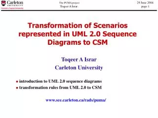
Transformation of Scenarios represented in UML 2.0 Sequence Diagrams to CSM. Toqeer A Israr Carleton University. introduction to UML 2.0 sequence diagrams transformation rules from UML 2.0 to CSM www.sce.carleton.ca/rads/puma/. Conceptual High Level View.

E N D
Transformation of Scenarios represented in UML 2.0 Sequence Diagrams to CSM Toqeer A Israr Carleton University • introduction to UML 2.0 sequence diagrams • transformation rules from UML 2.0 to CSM • www.sce.carleton.ca/rads/puma/
Conceptual High Level View Create Input Output Eclipse Eclipse Eclipse Navigate annotated UML model Apply Profile Java Create UML 2.0 model represented as internal data structure Annotated model with performance annotations Generate CSM objects(in Java) XMI XMI XML
Simple Interaction Diagram Message Interaction sd S s:CA t:CB Lifeline EventOccurrence (receiving) m1 Gate Event Occurrence Execution Occurrence Event Occurrence (sending)
ref ref EstablishAccess(“Illegal PIN”) OpenDoor Complex Interaction Diagram sd C User :System Interaction Occurrence CardOut opt msg(“Please Enter”) Combined Fragment
sd S1 . . . . . . s:CA t:CB Step::x1’ . . . . . . . . . Step::x1 Seq Step::x1 x1’ Step::x2 Seq m1 Step::x2 x1 x2 Step::x2 Seq . . . x1” . . . Step::x1” Notation: Seq . . . Synchronous message between passive objects
sd S2 <<PAresource>> s:CA <<PAresource>> t:CB . . . . . . m1 x1 x2 Synchronous Message between objects stereotyped <<Paresource>> Component s was acquired before x1 Processing Resource:: CPU . . . Processing Resource:: CPU Component: s Step::x1 ResAcq:: Component: t Step:x2 ResRel:: . . .
sd SA Step::x1’ s:CA t:CB Fork x1’ Step:x2 Step:x1” m1 x1 x1’’ x2 Step::x1 Fork Step:x2 . . . Asynchronous Message
Step::x1’ Fork Step:x3 Step:x2 Asynchronous Message (cont) sd SA s:CA t:CB m1 x1 m2 x2 x3
x1 x2 x3 Asynchronous message between components stereotyped <<PAresource>> sd SA2 Component s was acquired before x1 <<PAresource>> s:CA <<PAresource>> t:CB Processing Resource:: CPU . . . . . . . . . Step::x1 Component: s m1 Processing Resource:: CPU m2 Fork Step:x2 ResAcq:: Component: t . . . Step:x3 . . .
sd CF x2 x3 x1 x4 Interaction Diagram – Combined Fragment Component s was acquired before x1 Processing Resource:: CPU . . . s:CA t:CB Step::x1 m1 ResAcq:: Component: s Step::x2 alt value > 0 m2 ResRel:: Branch ResAcq:: ResAcq:: [else] m3 Step::x3 Step::x3 Component: t ResRel:: ResRel:: . . . . . . Processing Resource:: CPU
sd IO . . . Processing Resource:: CPU s:CA t:CB Step::x1 Processing Resource:: CPU m1 ResRel:: x2 Component: t ResAcq:: x1 ref Step::x2 y Component: s ResRel:: ResAcq:: Step::y . . . Interaction Diagram – Interaction Occurrence
Accomplished Created UML 2.0 diagrams in Eclipse programmatic approach using UML2 plug-in Defined & applied the UML Performance Profile Work In Progress Implementation of the transformation rules from sequence and deployment diagrams to CSM Testing / Validation Future Work Express the above transformation in MOF QVT, if possible Status