Download
1 / 18

E N D
1. Introduction to Composites
3. Composite Structures
4. TERMINOLOGY/CLASSIFICATION
5. Types of composites
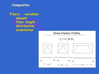
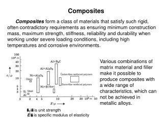
6. Particle and Fiber variables For any composite, regardless of the selection of matrix and disperse phase (material and type), there are many options that will affect properties:
7. Particle Reinforced Composites
8. Large particle composites Large particle composites
Involves large particles that are harder or stiffer than matrix.
The matrix transfers applied stress to the particles, which thus bear a fraction of the load.
Bonding at the interface is necessarily important.
Particles should be:
Equiaxed
Uniformly distributed
Properties generally determined by the rules of mixtures.
9. COMPOSITE SURVEY: Particle-II
10. Large Particle Composite Examples Cermets (not cements) are ceramic-metal composites
Cermented Carbide�cutting tools
WC or TiC particles (incredibly hard)
Metal matrix (Co or Ni)
The particles will crack under the high stresses in cutting applications, so the matrix prevents crack propagation between particles by separating them.
Up to 90 volume percent of particles.
Polymer/Carbon composites include
Tires
Elastomer matrix with carbon black particles (15-30 vol%).
Improved tensile strength, tear and abrasion resistance, and toughness.
Small particles are optimal, <50 nm.
Ceramic-ceramic composites include
Concrete is:
~70 vol% sand and gravel particles (different sizes promotes better packing).
Portland cement is the binder once water is added.
Improved tensile, compressive, and shear response by reinforcing with steel rods, bars (rebar), wires, or wire mesh (ceramic-ceramic-metal composite).
Steel is selected for thermal expansion coefficient
Not corroded during cement hardening
Strong composite/matrix bond is possible, especially if the steel surface is contoured
Pre stressing
11. Dispersion strengthened (higher tech�) Similar to precipitation hardening
Strengthening is not as good as for precipitation hardening at low temperatures
At higher temperatures the properties are generally better.
Particles are selected to be unreactive (no precipitate growth or dissolution of the precipitate).
Dispersion strengthened composites
Small particles (10 to 100 nm)
Matrix bears most of the applied load
Particles hinder or impede motion of dislocations
Plastic deformation is restricted
Improves yield and tensile strength.
Examples
Thoria dispersed nickel (Ni with up to 3 vol% ThO2 particles)
Sintered aluminum powder (Al matrix with Al2O3 coated Al flakes)
13. Fiber composites Why are we using fibers?
Especially for ceramics, due to Weibull statistics the fracture strength of a small part is usually greater than that of a large component (smaller volume=fewer flaws=fewer big flaws).
Fibers come in three forms
Whiskers (graphite, SiC, Si3N4, Al2O3)
Single crystals
Huge length/diameter
Small, so nearly flaw free
Strongest known materials
expensive
Fibers (aramids, glass, carbon, boron, Si3N4, Al2O3)
Polycrystalline or amorphous
Small diameter
Wires (usually metals)
Large diameter
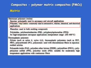
14. Matrix phase Usually a metal or polymer since some ductility is desirable
Serves several functions for fiber composites
Bonds with the fibers (Very important).
Protect fibers from surface damage due to abrasion or corrosion (i.e., avoid cracks on surfaces of fibers).
Separate the fibers.
Prevent propagation of brittle cracks between fibers.
15. Fiber Reinforced Most common composite type.
Generally applied for improved strength and stiffness with respect to weight
Aerospace applications
High value sporting goods
Since the load cannot be transferred beyond the end of the fiber, there is a critical fiber length (Lc) for effective strengthening and stiffening that will depend on:
d, the fiber diameter; sf*, the fiber ultimate tensile strength; and on tauc, either the matrix/fiber bond strength or the matrix shear yield strength (whichever is smaller).
The bond between the matrix and the fiber dictates whether the fiber will improve the properties of the composite by transferring an applied load to the fiber.
16. Stress along a fiber For L=Lc, the maximum fiber load is achieved at the center of the fiber length.
For L>Lc, the maximum fiber load is carried by most of the fiber. These are considered to be �Continuous� fibers and are optimal.
For L<Lc, the maximum fiber load is never reached, so that a weaker, cheaper and longer fiber or even particles could have been used instead.
17. Optimal fiber length So, as fibers get longer and thinner, the overall properties of the composite are improved.
Optimal fiber lengths are usually about 30*Lc.
18. SUMMARY What is the matrix in a composite and what materials are commonly used as a matrix?
What are the possible strengthening mechanisms for particle reinforced composites (there are 2)?
Be able to calculate upper and lower bounds for the Young�s modulus of a large particle composite.
Know the equation for the critical length (Lc) of a fiber.
Know the stress distribution on fibers of various lengths w/r Lc in a composite.