Download

1 / 17
200 likes | 521 Views
Active Detuning of Inductively Coupled Surface Coils. Jolinda Smith Lewis Center for Neuroimaging University of Oregon. Inductive coupling. Tuned coil is inductively coupled to a matching loop No physical connection to tuned coil. Inductive coupling. Easy to construct Balanced

E N D
Active Detuning of Inductively Coupled Surface Coils Jolinda Smith Lewis Center for Neuroimaging University of Oregon
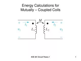
Inductive coupling • Tuned coil is inductively coupled to a matching loop • No physical connection to tuned coil
Inductive coupling • Easy to construct • Balanced • Especially useful for implanted and cryocooled coils • Kuhns, P. L., M. J. Lizak, et al. (1988). "Inductive Coupling and Tuning in Nmr Probes - Applications." Journal of Magnetic Resonance78(1): 69-76. • Hoult, D. I. and B. Tomanek (2002). "Use of mutually inductive coupling in. probe design." Concepts in Magnetic Resonance15(4): 262-285.
Need for decoupling • When using separate transmit and receive coils, they must be decoupled from each other. • Failure to do so results in nonuniform flip angles and image artifacts. Decoupled Not decoupled
Approaches to decoupling • Geometric decoupling • Passive detuning with crossed diodes • Optical detuning with photodiodes • Active detuning with pin diodes
Pin diode detuning • Active detuning uses pin diodes to detune the receive coil during the transmit phase. • Biasing pin diode creates resonant circuit; coupling to this circuit shifts resonance of coil L C
Use a third coil • Third coil is switched into resonance by biasing on a pin diode • Coupling of detuning coil with receive coil shifts resonance peak • Analogous to pin diode detuning of capacitively coupled coils Wong W H, Rath A R, “Detunable coil assembly and method of detuning RF coil for MRI”, US Patent no. 6,552,544 (2003)
Inductively coupled coil with active detuning Pin diode off Receive coil diameter = 1 inch Detuning coil diameter = 1.25 inches Pickup coil diameter = 0.75 inches Height of stack = 0.5 inches Pin diode on
Inductively coupled coil with Helmholtz pair transmit Without detuning With detuning Spin echo images of water-filled phantom -51 dB S21, transmit coil on port 1, receive coil on port 2 -26 dB
Inductively coupled coil with birdcage transmit coil Without detuning With detuning Spin echo images of water-filled phantom -49 dB S21, transmit coil on port 1, receive coil on port 2 -15 dB
Small surface coils with birdcage transmit coil Capacitively coupled coil with active detuning Inductively coupled coil with passive detuning Inductively coupled coil with active detuning Spin echo images of water-filled phantom SNR maps
Human finger joint images 1 2 1) 3D VIBE, res = 0.26 mm, sl th = 0.5 mm. 2) 3D FLASH, res = 0.20 mm, sl th = 0.3 mm. 3) TSE, res = 0.20 mm, sl th = 0.5 mm. 4) TOF3D, res = 0.20 mm, sl th = 1 mm. 3 4
Ex vivo mouse brain at 3T 3D flash, in plane resolution 75 m, slice thickness 100 m, TR = 68 ms, TE = 13 ms, flip angle = 30°, 64 slices, 32 averages, total scan time = 9 hours
Conclusions • Inductively coupled coils may be actively detuned by adding a third detuning coil controlled by pin diodes • These coils are easy to construct and show no loss in SNR compared to coils using other methods of decoupling.
Acknowlegments • Ray Nunnally, LCNI • Scott Watrous, LCNI • Cliff Dax, TSA, University of Oregon • Felicia Katz, California Institute of Technology
Geometric decoupling Well aligned 1° offset 2° offset -45 dB -37 dB -31 dB
Geometric decoupling • Place receive coil orthogonal to transmit RF field • Advantages: conceptually simple, no additional components needed • Disadvantages: Alignment must be precise