Download
1 / 39
390 likes | 707 Views
Computer Data Storage (Internal Representation) Chapter 1 Winter 2005. Summary. A flip-flop is a means of storing a bit in an electronic circuit. Gates are electronic circuits which can be used to build a flip-flop or other circuits which perform addition of bits, etc.

E N D
Computer Data Storage (Internal Representation) Chapter 1 Winter 2005
Summary • A flip-flop is a means of storing a bit in an electronic circuit. • Gates are electronic circuits which can be used to build a flip-flop or other circuits which perform addition of bits, etc. • The gates: AND, OR, XOR, and NOT are examples of Boolean operators. • In actual circuits a 1 corresponds to an on voltage (usually 3.2 volts or 5 volts) while a 0 is off, or 0 volts.
Sect. : Main Memory • The principle reservoir of memory (places to hold bits) is called main memory. • Main memory is arranged in cells, typically of size 8 bits, or 1 byte. These are arranged in consecutive order, each cell having its own address. • The computer can access these cells through a read operation, or a write operation, in any order (random access memory or RAM) • The total number of cells is arranged in powers of 2: Usually in kilobytes (KB), megabytes (MB), gigabytes(GB), terabytes, . . . These are 1024 bytes (210), 1,048,576 bytes (220), 1024 MB (230), etc.
Main Memory con’t • Within each cell we assign an order to the bits: one side is the “most significant bit” (high-order end) and the other is the “least significant bit” (low-order end, i.e. the 1’s column).
Sect. 1.3: Mass Storage • RAM is the working memory of a computer. It’s not often large (64 to 256 MB typically) and isn’t maintained while the computer is turned off. But, it is typically fast ( nanoseconds or 1x10⁻⁹seconds) • Mass storage is also a reservoir of places to store bits only it is typically large (40GB is common now) “permanent”, not lost while power is off, and slow ( milliseconds access times 1x10⁻³ seconds) often requiring mechanical motion to access memory (i.e. a “hard drive”).
Mass Storage con’t • Magnetic disks (hard drive) • Similar to magnetic cores but instead of small doughnuts now we use magnetic material on a hard disk. Bits are written along a circular track by a read/write head which is a mechanical arm. When a new track is written, the head moves to a new cylinder. Each track is divided into arcs called sectors. Each track within a particular disk system contains the same number of sectors and each sector contains the same number of bits. Typically a sector is 512 bytes. (Sometimes also called a block.) • When we decide where the cylinders,tracks and sectors are we are said to have formatted the disk.
Mass Storage con’t • Disk storage systems can be either “hard disk” or “floppy disk”. This just refers to the type of disk used. Typically “hard disks” have multiple hard disks arranged in a stack, each with its own read/write head. • A disk’s performance is measured in terms of 1) seek time (time required to move the head from one track to another), 2) rotation delay or latency time (half the time required for the disk to make a complete rotation), 3) access time (the sum of seek time and rotation delay), and 4) transfer rate (rate at which data can be transferred to or from the disk).
Other Forms of Mass Storage • Compact disks • CD-DA (compact disk - digital audio) • CD-ROM (compact disk - read-only memory) 650MB • DVD - ROM (digital versatile disk - read only memory) 10 GB • DVD - RAM (digital versatile disk - random access memory) • Magneto-optical disk (200MB - 4 GB) • Magnetic Tape (25 GB) (typically used for “backing up” systems)
Other Storage Techniques • Magnetic cores • Used in very early computers and in military electronics. • Data is not lost when the power is turned off • Magnetic cores aren’t as easily destroyed by an airburst nuclear explosion (EMP) • Capacitors • Either charged or discharged • Must be “refreshed” many times per second -- dynamic memory (DRAM)
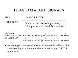
File Storage and Retrieval • Information is stored on mass storage systems as files. i.e. a complete document, image, email, etc. • Mass storage systems manipulate whole sectors. When referring to this block of information on the disk we call this a physical record. A file will then typically be made up of many physical records (will be recorded over many sectors). • Groups of data (files) are then further divided into logical records. • Buffer • Fragmentation • Virtual memory
Machine Architecture(The ideas which allow us to compute) • How do we store information on a piece of Silicon? • Digital versus Analog information • Encoding of data (decimal,binary, hexadecimal) • How do we manipulate that data? • i.e. how can we add two numbers
Digital & Analog Information • Computers are digital-- What does that mean? • Digital information is: • Robust (easy to handle without errors) • Low noise • Example: Digitization of audio • Audio digitization software (SoundView for the Mac -- http://www.physics.swri.edu/SoundView/SoundView.sit.hqx)
The process for digital audio goes something like this: At the recording studio analog signal digitized sound 5 7 3 0 7 9……… encode to binary |0101|0111|0011|0000|0111|1001|…… record bits on CD “burning” a CD On your CD player read bits on CD |0101|0111|0011|0000|0111|1001|…… decode 5 7 3 0 7 9……… play sound analog signal
0 1 • Bit -- “A binary digit” • A “box” which can hold only the values 0 and 1 Bits are easy to store on CDs as tiny pits, or spots, burned by a laser.
Binary Counting • 0 • 1 1 one = 1 • Out of digits, must carry • 10 1 two , 0 ones = 2 • 11 1 two, 1 one = 3 • Out of digits in 2’s column, carry • 100 1 four, 0 twos, 0 ones = 4 • 101 1 four 0 twos 1 one = 5 • 110 1 four, 1 two, 0 one = 6
Integer to Binary conversion: figs. 1.15 and 1.16 Step 1: Divide the value by two and record the remainder. Step 2: As long as the quotient obtained is not zero, continue to divide the newest quotient by two and record the remainder. Step 3: Now that a quotient of zero has been obtained, the binary representation of the original value consists of the remainders listed from right to left in the order they were recorded. (This is an algorithm)
Characters • Characters correspond to letters or symbols • ASCII code look-up table (Appendix A, p. 539) • (space) 00100000 • ! 00100001 • “ 00100010 • ….. …….. • W 01010111 • and so on ……. • Hello = 01001000|01100101|01101100|01101100|01101111
Operations on Bits • We would like to be able to compare bits • logical operations • AND, OR, NOT, XOR • We need to be able to add bits
Storing a bit • Storing a bit within a machine requires a device that can be in one of two states. We’ve seen how to do this on a CD, namely with a pit burned by a laser. This, however, is permanent. Furthermore, you can’t flip a bit in order to, say, compute the 2’s complement, or add two binary sequences. A computer must have available a means of both storing a bit and changing it.
More than couple bits • Hello 01001000110010101101100011011000110111100101110 • Long and confusing - humans can only handle small sets of bits • Hexadecimal system allows easier readingof bit patterns • Base 16
Section 1.1: Storage of Bits Value 4-bit Hex. 0 0000 0 1 0001 1 2 0010 2 3 0011 3 4 0100 4 5 0101 5 6 0110 6 7 0111 7 8 1000 8 9 1001 9 10 1010 A 11 1011 B 12 1100 C 13 1101 D 14 1110 E 15 1111 F • Is there an easier way to write all those 1’s and 0’s? • Yes -- Hexadecimal notation: • (base 16) Example: 2 byte (16-bit) 0010 | 0111 | 1111 | 0001 | = ? D70B = ?
Hexadecimal con’t • 1100010 8 bit • 1100 0100 • C 4 • 1100010010101111 16 bit • 1100 0100 1010 1111 • C 4 A F • 11000100101011110011010111100110 32 bit • 1100 0100 1010 1111 0011 0101 1110 0110 • C 4 A F 3 5 D 6
Sect. 1.5The Binary System • Let’s take a closer look at the Binary System Addition Rules of addition 0 1 0 1 + 0 + 0 + 1 + 1 0 1 1 1 0 see fig. 1.17, p. 45 Adding two numbers using binary patterns (don’t say binary numbers because binary sequences can correspond to characters, which you could add as well) This is a carry, not a “ten”
Storing fractions in binary • Radix point • Plays the same role as the decimal point in decimal notation • Addition is carried out the same as for binary sequences representing integers (just align the radix points).
Sect. Storing Integers (How to represent positive and negative integers at the same time) • Two’s Complement Notation • a method compatible with digital circuitry • negative numbers 3-bit 3 011 2 010 1 001 0 000 -1 111 -2 110 -3 101 -4 100 If the left most bit is a 1 then it represents a negative number
Examples of 2’s Complement Representation • Starting with the binary representation of a positive integer, find the representation of its negative counterpart. • Copy and flip method • 1’s Complement and add 1 method • Addition in 2’s complement • Subtraction in 2’s complement • Overflow errors
Storing non-integers • We’ve seen how to represent integers (i.e. whole numbers), characters, and fractions by binary sequences. Now we look at how to represent non-integer numbers in binary. • Floating point numbers are numbers like 5.234 or 0.127 • For larger or smaller numbers we use scientific notation or engineering notation +123456.9 == +1.234569 x 105 == +1.234569E5 -0.0001234 == -1.234 x 10-4 == -1.234E-4 signmantissaexponent
Floating point numbers (con’t) +123456.9 == +1.234569 x 105 == +1.234569E5 -0.0001234 == -1.234 x 10-4 == -1.234E-4 signmantissaexponent The exact way we represent the mantissa and exponent can be complicated. The algorithm used depends on the precision required. Typically we have either 32 or 64-bit sequences. We won’t go into the details here. 8-bit binary sequence The binary sequence is broken up into 3 sections.
Full Adder Abstraction
Sect. : Communication Errors • Any time we have multiple computers or multiple devices that are connected by cables, wires or radio waves we must transmit binary sequences in order to transfer information. Environmental factors such as dirt, water, electrical interference (including sunspots!) are unavoidable. These can cause errors to arise in the transmission. What can we do about these errors?
Communication Errors con’t • Create a scheme where we can detect errors. • Add to this a scheme where we can correct errors.
Parity Bits • One way of detecting errors is to add a parity bit to a sequence of bits. • For example, consider an odd parity system: • For each binary sequence add one bit. This bit is a 1 if there are an even number of 1’s in the original binary sequence. Make this bit a 0 if there are an odd number of 1’s. • The point is to make every binary sequence have an odd number of 1’s. • After transmission we check the parity of the incoming sequences. If any sequence has an even number of 1’s (even parity) then we encountered an error. • Q: If all received sequences have odd parity can we be sure no errors occurred?
Error Correcting Codes • Q: Can we correct a message with errors in it even if we don’t know the original message? • Yes, to an extent. • Hamming distance • First, create a code. This code has the property that every member is represented by a binary sequence that is different from all the other members in a special way. Each member has a Hamming distance of at least 3. The Hamming distance is the number of bits in which two binary sequences differ, column by column. See example. http://www.princeton.edu/~matalive/VirtualClassroom/v0.1/html/lab2/lab2_5.html • Second, encode your information using this code. • Transmit your data
Error Correcting Codes, con’t • Decode the data using the code. If any one sequence doesn’t match to a legal binary sequence in the code, an error has occurred. • Finally, to correct the error we compare the received code with the code table. If we find that our received code differs by one bit from a legal sequence then we assume this legal sequence, which represents a certain character, is what was originally sent -- so we substitute it in. • This last step assumes that only 1 error happened. But there are ways of solving this problem too. We can simply increase the Hamming distances between all members of our code. That way we could account for more errors.