Download
1 / 90
920 likes | 1.42k Views
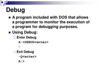
Debug. A program included with DOS that allows a programmer to monitor the execution of a program for debugging purposes. Using Debug: Enter Debug A:>DEBUG<enter> - Exit Debug -Q<enter> A:>. Debug. Displaying registers -R<enter>

E N D
Debug • A program included with DOS that allows a programmer to monitor the execution of a program for debugging purposes. • Using Debug: • Enter Debug A:>DEBUG<enter> - • Exit Debug -Q<enter> A:>
Debug • Displaying registers -R<enter> AX=0000 BX=0000 CX=0000 DX=0000 SP=FFEE BP=0000 SI=0000 DI=0000 DS=0D00 ES=0D00 SS=0D00 CS=0D00 IP=0100 NV UP DI PL NZ NA PO NC 0D00:0100 B80100 MOV AX,0001 • Modifying registers -R CX:<enter> CX 0000 :0009<enter> -R CX<enter> CX 0009 :<enter> -
Debug • Assemble command – allows the programmer to enter assembly language instructions into memory. -A 100<enter> 0B3C:0100 MOV AX,1<enter> 0B3C:0103 MOV BX,2<enter> 0B3C:0106 ADD AX,BX<enter> 0B3C:0108 INT 3<enter> 0B3C:0109<enter> -
Debug • Unassemble command - allows the programmer to display the machine code in memory along with their assembly language instructions. -U 100 L1<enter> 0B3C:0100 B80100 MOV AX,1 -U 100 103 0B3C:0100 B80100 MOV AX,1 0B3C:0103 BB0200 MOV BX,2 -
Debug • Go command – allows the programmer to execute instructions found between two given addresses. -G=100 108<enter> AX=0004 BX=0003 CX=0000 DX=0000 SP=FFEE BP=0000 SI=0000 DI=0000 DS=0B3C ES=0B3C SS=0B3C CS=0B3C IP=0108 NV UP EI PL NZ NA PO NC 0B3C:0108 CC INT 3
Debug • Trace command - allows the programmer to trace through the execution of a program one or more instructions at a time to verify the effect the program has on registers and/or data. -T=100 2<enter> AX=0001 BX=0000 CX=0000 DX=0000 SP=FFEE BP=0000 SI=0000 DI=0000 DS=0B3C ES=0B3C SS=0B3C CS=0B3C IP=0103 NV UP EI PL NZ NA PO NC 0B3C:0103 BB0200 MOV BX,0002 AX=0001 BX=0003 CX=0000 DX=0000 SP=FFEE BP=0000 SI=0000 DI=0000 DS=0B3C ES=0B3C SS=0B3C CS=0B3C IP=0106 NV UP EI PL NZ NA PO NC 0B3C:0106 01D8 ADD AX,BX -
Debug • Dump command (D) - allows the programmer to examine the contents of memory. • Fill command (F) - allows the programmer to fill memory with data. • Enter command (E) - allows the programmer to modify memory content. -F 100 LF 00<enter> -D 100 LF 0B3C:0100 00 00 00 00 00 00 00 00 00 00 00 00 00 00 00 00 ……………. -F 110 11F 20 -D 100 11F 0B3C:0100 00 00 00 00 00 00 00 00 00 00 00 00 00 00 00 00 ……………. 0B3C:0110 20 20 20 20 20 20 20 20 20 20 20 20 20 20 20 20 -F 120 LF 20 -E 120 ‘John Smith’ -D 120 LF 0B3C:0120 4A 6F 68 6E 20 53 6E 69 74 68 20 20 20 20 20 20 John Smith -
Debug • Loading programs from a specific file requires two commands, the Name command, N, and the Load command, L. -N A:\PROG1.EXE -L • Loading programs upon entering Debug. C:\DEBUG A:\PROG1.EXE
Debug • Links to useful websites: • DEBUG/ASSEMBLY TUTORIAL by Fran Golden • http://www.datainstitute.com/debug1.htm • Rough Guide to Assembly • http://www.geocities.com/riskyfriends/prog.html • Paul Hsieh’s x86 Assembly Language Page • http://www.azillionmonkeys.com/qed/asm.html
Assembly LanguageProgram • Series of statements which are either assembly language instructions or directives. • Instructions are statements like ADD AX,BX which are translated into machine code. • Directives or pseudo-instructions are statements used by the programmer to direct the assembler on how to proceed in the assembly process.
Assembly LanguageProgram • Statement format: • [label:] mnemonic [operands][;comments] • Label: • Cannot exceed 31 characters. • Consists: • Alphabetic characters both upper and lower case. • Digits 0 through 9. • Special characters ( ? ), ( . ), ( @ ), ( _ ), and ( $ ). • The first character cannot be a digit. • The period can only be used as the first character, but its use is not recommended. Several reserved words begin with it in later versions of MASM.
Assembly LanguageProgram • Label: • Must end with a colon when it refers to an opcode generating instruction. • Do not need to end with a colon when it refers to a directive. • Mnemonic and operands: • Instructions are translated into machine code. • Directives do not generate machine code. They are used by the assembler to organize the program and direct the assembly process.
Assembly LanguageProgram • Comments: • Begin with a “;”. • Ignored by the assembler. • Maybe be on a line by itself or at the end of a line: • ;My first comment • MOV AX,1234H ;Initializing…. • Indispensable to the programmers because they make it easier for someone to read and understand the program.
Segment Definition • The CPU has several segment registers: • CS (code segment). • SS (stack segment). • DS (data segment). • ES (extra segment). • FS, GS (supplemental segments available on 386s, 486s and Pentiums. • Every instruction and directive must correspond to a segment. • Normally a program consists of three segments: the stack, the data, and the code segments.
Segment Definition • Model definition. • .MODEL SMALL • Most widely used memory model. • The code must fit in 64k. • The data must fit in 64k. • .MODEL MEDIUM • The code can exceed 64k. • The data must fit in 64k. • .MODEL COMPACT • The code must fit in 64k. • The data can exceed 64k. • MEDIUM and COMPACT are opposites.
Segment Definition • .MODEL LARGE • Both code and data can exceed 64k. • No single set of data can exceed 64k. • .MODEL HUGE • Both code and data can exceed 64k. • A single set of data can exceed 64k. • .MODEL TINY • Used with COM files. • Both code and data must fir in a single 64k segment.
Segment Definition • Segment definition formats: • Simplified segment definition. • Full segment definition. • The Simplified segment definition uses the following directives to define the segments: • .STACK • .DATA • .CODE • These directives mark the beginning of the segments they represent.
Segment Definition • The full segment definition uses the following directives to define the segments: • Label SEGMENT [options] ;Statements belonging to the segment. Label ENDS • The label must follow naming conventions previously discussed.
Program Termination • With PC: • MOV AH,4CH INT 21H • Always return control to the OS.
Text Editors • Use the following text editors to write your programs. • Notepad (Windows). • Edit (DOS). • Or any other editor capable of generating ASCII files.
DOS and BIOS Interrupts • DOS and BIOS interrupts are used to perform some very useful functions, such as displaying data to the monitor, reading data from keyboard, etc. • They are used by identifying the interrupt option type, which is the value stored in register AH and providing, whatever extra information that the specific option requires.
BIOS Interrupt 10H • Option 0H – Sets video mode. • Registers used: • AH = 0H • AL = Video Mode. • 3H - CGA Color text of 80X25 • 7H - Monochrome text of 80X25 • Ex: • MOV AH,0 • MOV AL,7 • INT 10H
BIOS Interrupt 10H • Option 2H – Sets the cursor to a specific location. • Registers used: • AH = 2H • BH = 0H selects Page 0. • DH = Row position. • DL = Column position. • Ex: • MOV AH,2 • MOV BH,0 • MOV DH,12 • MOV DL,39 • INT 10H
BIOS Interrupt 10H • Option 6H – Scroll window up. This interrupt is also used to clear the screen when you set AL = 0. • Registers used: • AH = 6H • AL = number of lines to scroll. • BH = display attribute. • CH = y coordinate of top left. • CL = x coordinate of top left. • DH = y coordinate of lower right. • DL = x coordinate of lower right.
BIOS Interrupt 10H • Clear Screen Example: • MOV AH,6 • MOV AL,0 • MOV BH,7 • MOV CH,0 • MOV CL,0 • MOV DH,24 • MOV DL,79 • INT 10H • The code above may be shortened by using AX, BX and DX registers to move word size data instead of byte size data.
DOS Interrupt 21H • Option 1 – Inputs a single character from keyboard and echoes it to the monitor. • Registers used: • AH = 1 • AL = the character inputted from keyboard. • Ex: • MOV AH,1 • INT 21H
DOS Interrupt 21H • Option 2 – Outputs a single character to the monitor. • Registers used: • AH = 2 • DL = the character to be displayed. • Ex: • MOV AH,2 • MOV DL,’A’ • INT 21H
DOS Interrupt 21H • Option 9 – Outputs a string of data, terminated by a $ to the monitor. • Registers used: • AH = 9 • DX = the offset address of the data to be displayed. • Ex: • MOV AH,09 • MOV DX,OFFSET MESS1 • INT 21H
DOS Interrupt 21H • Option 4CH – Terminates a process, by returning control to a parent process or to DOS. • Registers used: • AH = 4CH • AL = binary return code. • Ex: • MOV AH,4CH • INT 21H
80386 • General purpose processor optimized for multitasking operating systems. • Supports 32 bits address and data buses. • Capable of addressing 4 gigabytes of physical memory and 64 terabytes of virtual memory.
Registers • General purpose registers. • There are eight 32 bits registers (EAX, EBX, ECX, EDX, EBP, EDI, ESI, and ESP). • They are used to hold operands for logical and arithmetic operations and to hold addresses. • Access may be done in 8, 16 or 32 bits. • There is no direct access to the upper 16 bits of the 32 bits registers. • Some instructions incorporate dedicated registers in their operations which allows for decreased code size, but it also restricts the use of the register set.
Registers • Segment registers. • There are six 16 bits registers (CS, DS,ES,FS,GS, and SS). • They are used to hold the segment selector. • Each segment register is associated with a particular kind of memory access.
Registers • Other registers. • EFLAGS controls certain operations and indicates the status of the 80836 (carry, sign, etc). • EIP contains the address of the next instruction to be executed. • The E prefix in all 32 bits registers names stands for extended.
Effective, Segment and Physical Addresses • Effective address (EA). • Also called offset. • Result of an address computation. • Segment address (SA). • Also called segment selectors. • Addresses stores in segment registers • Physical address (PA). • Location in memory. • PA = SA * 16 + EA
Memory Organization • Sequence of bytes each with a unique physical address. • Data types: • Byte. • Word. • Double word.
Little Endian Notation • The 80386 stores the least significant byte of a word or double word in the memory location with the lower address.
Constants • EQU is used to define constants or to assign names to expressions. • Form: • Name EQU expression. • Examples: • PI EQU 3.1415 • Radius EQU 25 • Circumference EQU 2*PI*Radius
Variables • DB - define byte. • DW - define word. • DD – define double word. • Form: • Variable Directive oper, . . ,oper • Examples: • Alpha db ‘ABCDE’ • Alpha2 db ‘A’,’B’,’C’,’D’,’E’ • Alpha3 db 41h,42h,43h,44h,45h • Word1 dw 3344h • Double_word1 dd 44332211h
Addressing Modes • These are the different ways in which data may be accessed by the microprocessor. • Immediate. • Register. • Memory. • Direct. • Register indirect. • Register relative. • Based indexed. • Relative based indexed.
Immediate • Directly accessible to the EU. • The address is part of the instruction. • Useful in initializations. • MOV EAX,1111000B • MOV CL, 0F1H
Register • Directly accessible to the EU. • Most compact and fastest executing instructions. • Operands are encoded in the instruction. • MOV EBX,EDX • MOV AL,CL
Memory • When reading or writing to memory the execution unit passes an offset value, the effective address, to the bus interface unit which then computes the physical address.
Direct • Simplest memory addressing mode. • Access to simple variables. • MOV EAX,DS:SUM • MOV CL,DS:COUNT+5 • MOV DS:[500H],EDX
Register Indirect • MOV EAX, DS:[EBX] • MOV DS:[EDI],EDX
Register Relative • Access to one dimensional arrays. • MOV EAX,DS:ARRAY[EBX] • MOV DS:MESSAGE[EDI], DL
Relative Based Indexed • Used to access two dimensional arrays or arrays contained in structures. • MOV DS:ARRAY[EBX][EDI],EAX
Accessing Arrays • One dimensional arrays. • MOV DS:ARRAY[ESI*SF],EDX • SF = Scaling factor for data size. • Two dimensional arrays. • MOV DS:ARRAY[EBX*SF*SR][ESI*SF],EDX • SF = Scaling factor for data size. • SR = Size of row.