Download
1 / 19
300 likes | 1.58k Views
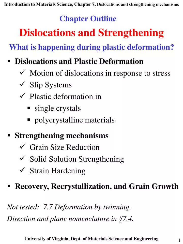
Chapter Outline. Dislocations and Strengthening What is happening during plastic deformation?. Dislocations and Plastic Deformation Motion of dislocations in response to stress Slip Systems Plastic deformation in single crystals polycrystalline materials

E N D
Chapter Outline Dislocations and Strengthening What is happening during plastic deformation? • Dislocations and Plastic Deformation • Motion of dislocations in response to stress • Slip Systems • Plastic deformation in • single crystals • polycrystalline materials • Strengthening mechanisms • Grain Size Reduction • Solid Solution Strengthening • Strain Hardening • Recovery, Recrystallization, and Grain Growth • Not tested: 7.7 Deformation by twinning, • Direction and plane nomenclature in §7.4.
Introduction How do metals plastically deform? Why does forging change properties? Why deformation occurs at stresses smaller than those for perfect crystals? Taylor, Orowan and Polyani 1934 : Plastic deformation due to motion of large number of dislocations. Plastic deformation under shear stress
Dislocations allow deformation at much lower stress than in a perfect crystal Top of crystal slipping one plane at a time. Only a small of fraction of bonds are broken at any time. Propagation of dislocation causes top half of crystal to slip with respect to the bottom. The slip plane – crystallographic plane of dislocation motion.
Direction of Dislocation Motion Edge dislocation line moves parallel to applied stress Screw dislocation line moves perpendicular to applied stress Mixed dislocations: direction is in between parallel and perpendicular to applied shear stress
Strain Field around Dislocations Strain fields from distortions at dislocations: Drops radially with distance. Edge dislocations compressive, tensile, and shear lattice strains. Screw dislocations shear strain only.
Interactions between Dislocations Strain fields around dislocations cause them to exert force on each other. Direction of Burgers vector Sign Same signs Repel Opposite signs Attract (annihilate)
Where do Dislocations Come From ? Dislocation density dislocation length/ volume OR number of dislocations intersecting a unit area. 105 cm-2 in carefully solidified metal crystals to 1012 cm-2 in heavily deformed metals. Most crystalline materials have dislocations due to stresses associated with the forming process. Number increases during plastic deformation. Spawn from dislocations, grain boundaries, surfaces. Picture is snapshot from simulation of plastic deformation in a fcc single crystal (Cu). See animation at http://zig.onera.fr/lem/DisGallery/3D.html
Slip System • Preferred planes for dislocation movement (slip planes) • Preferred crystallographic directions • (slip directions) • Slip planes + directions (slip systems) • highest packing density. • Distance between atoms shorter than average; distance perpendicular to plane longer than average. Far apart planes can slip more easily. BCC and FCC have more slip systems compared to HCP: more ways for dislocation to propagate FCC and BCC are more ductile than HCP.
Slip in a Single Crystal Each step (shear band) results from the generation of a large number of dislocations and their propagation in the slip system Zn
Resolving (Projecting) Applied Stress onto Slip System Dislocations move along particular planes and directions (the slip system) in response to shear stresses along these planes and directions Applied stress is resolved onto slip systems? Resolved shear stress, R, Deformation due to tensile stress, .
Slip in Single Crystals Critical Resolved Shear Stress Resolved shear stress increases crystal will start to yield (dislocations start to move along most favorably oriented slip system). Onset of yielding yield stress, y. Minimum shear stress to initiate slip: Critical resolved shear stress: Maximum of (cos cos) = = 45o cos cos = 0.5 y = 2CRSS Slip occurs first in slip systems oriented close to ( = = 45o) with respect to the applied stress
Plastic Deformation of Polycrystalline Materials Grain orientations with respect to applied stress are typically random. Dislocation motion occurs along slip systems with favorable orientation (i.e. highest resolved shear stress). Cu
Plastic Deformation of Polycrystalline Materials Larger plastic deformation corresponds to elongation of grains along direction of applied stress. Before After
Plastic Deformation of Polycrystalline Materials • Polycrystalline metals are typically stronger than single crystals. WHY? • Slip directions vary from crystal to crystal Some grains are unfavorably oriented with respect to the applied stress (i.e. cos cos low) • Even those grains for which cos cos is high may be limited in deformation by adjacent grains which cannot deform so easily • Dislocations cannot easily cross grain boundaries because of changes in direction of slip plane and disorder at grain boundary
Strengthening The ability of a metal to deform depends on the ability of dislocations to move Restricting dislocation motion can make material stronger • Mechanisms of strengthening in single-phase metals: • grain-size reduction • solid-solution alloying • strain hardening • Ordinarily, strengthening reduces ductility
Strengthening by grain-size reduction (I) Grain boundaries are barriers to dislocation motion: slip plane discontinues or change orientation. Small angle grain boundaries are not very effective. High-angle grain boundaries block slip and increase strength of the material.
Strengthening by grain-size reduction (II) Finer grains larger area of grain boundaries to impede dislocation motion: also improves toughness. Hall-Petch equation: o and ky constants for particular material d is the average grain diameter. 70 Cu - 30 Zn brass alloy d determined by rate of solidification, by plastic deformation and by heat treatment.
Solid-Solution Strengthening (I) Alloys usually stronger than pure metals Interstitial or substitutional impurities cause lattice strain and interact with dislocation strain fields hinder dislocation motion. Impurities diffuse and segregate around dislocation to find atomic sites more suited to their radii: Reduces strain energy + anchors dislocation Motion of dislocation away from impurities moves it to region where atomic strains are greater
Solid-Solution Strengthening (II) Smaller and larger substitutional impurities diffuse into strained regions around dislocations leading to partial cancellation of impurity-dislocation lattice strains.