Download
1 / 21
360 likes | 1.23k Views
Composite Beams and Columns. General Provisions. When determining load effects in members and connections of a structure with composite members consider effective sections at the time each increment of load is applied. Properties of the concrete and reinforcing steel are per ACI 318

E N D
General Provisions • When determining load effects in members and connections of a structure with composite members consider effective sections at the time each increment of load is applied. • Properties of the concrete and reinforcing steel are per ACI 318 • Available strength of members is from either plastic stress distribution or strain compatibility • Tensile strength of concrete is assumed to be zero
Plastic Stress Distribution • Available strength assumes steel has hit yield stress in either tension or compression, and the concrete in compression is at 085 f’c • This method is typically used for regular sections
Strain compatibility method • Linear strain distribution across the section is assumed. • Maximum concrete compressive strain of 0.003 is used • We use this method in Structures: Compressive
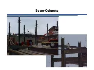
Encased composite columns • Cross-sectional area of steel must be at least 1% of total cross-section • Concrete encasement must be reinforced with continuous longitudinal bars and lateral ties/spirals • Transverse reinforcement ≥ 0.009 in2/in • Reinforcement ratio must be at least 0.004
Available Compressive Strength • For axial load encased column, limit case of flexural buckling • fc = 0.75 and Wc = 2.00 • P0 = nominal elastic compressive strength without length effects (kips) • As = area of steel section (in2) • Asr = area of continuous reinforcing bars (in2) • Ac = area of concrete (in2) • sy = yield strength of steel section (ksi) • syr = yield strength of reinforcement (ksi) • f’c = concrete compressive strength (ksi)
Elastic buckling strength • EIeff = effective rigidity of composite section (kip-in2) • K = effective length factor • L = laterally unbraced length of the member (in)
Effective rigidity • Es = modulus of steel (ksi) • Ec = modulus of concrete (ksi) • Is = moment of inertia steel section (in4) • Isr = moment of inertia reinforcement (in4) • Ic = moment of inertia concrete (in4)
Nominal compressive strength • If Pe ≥ 0.44 P0 • Else (Pe < 0.44 P0)
Shear Connectors • It is necessary to ensure that load is transferred from the concrete to the steel • Shear connectors accomplish this • Resist the shear force between the slab and beam • Prevent separation of the slab from the beam
Shear Connectors • Stud connectors are the most common in U.S. • Short round steel bar, welded to the beam at one end, with a head at the other end. • Diameter from 1⁄2 in. to 1 in. and lengths from 2 to 8 in. • The ratio of the length to diameter ≥ 4. • Most commonly used sizes are 3⁄4 in. or 7/8 in. dia. • Head diameter is 1⁄2 in. larger than stud and the head thickness is 3/8 in. or 1⁄2 in.
Shear studs • ASTM-A108, AISI Grades C1010, C1015, C1017 or C1020 cold-drawn steel with a minimum tensile strength of 60 ksi and a minimum elongation of 20% • specified in the AWS Structural Welding Code D1.1-75. • To prevent premature failure of studs because of tearing of base metal, the size of a stud not located over the beam web is limited to 2 1⁄2 times the flange thickness. • The strength of stud connectors increases with stud length up to a length of about four diameters and remains approximately constant for greater lengths
Equivalent shear force • V’ = required shear force • When external force is applied to the steel section • When external force is applied to the concrete encasement
Distribution • Shear connectors that can hold the required V’ must be distributed along the length for at least 2.5 times the depth of the encased column above and below the applied load • Maximum spacing is 16” • Connectors must be on at least 2 faces, symmetrically
Additional issues • At least four longitudinal bars must be used. • Transverse reinforcement must be spaced at the lesser of • 16 longitudinal bar diameters • 48 tie bar diameters • Half of the least dimension of the composite section • At least 1.5 inches of clear cover is required
Built-up Composite columns • If the steel section is built from two or more encased steel shapes, the shapes must be interconnected • Lacing • Tie plates • Batten plates • Etc • To prevent buckling of individual shapes
Shear strength of a connector • Asc = cross-sectional area of stud (in2) • Ec = modulus of concrete (ksi) • su = tensile strength of connector (ksi)
Floor beam Girder S L
Effective width b tc Yc hr tw d tf bf
Shear Connectors Concrete Slab Ribbed steel deck Steel section