Download
1 / 4

E N D
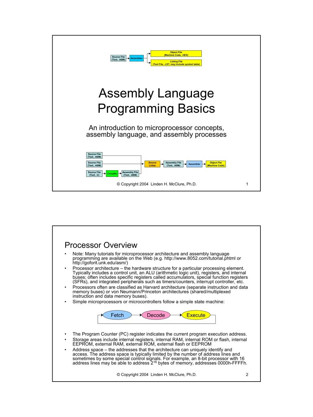
Object File (Machine Code, .HEX) Source File (Text, .ASM) Assembler Listing File (Text File, .LST, may include symbol table) Assembly Language Programming Basics An introduction to microprocessor concepts, assembly language, and assembly processes Source File (Text, .ASM) Source File (Text, .ASM) Source Linker Assembly File (Text, .ASM) Object File (Machine Code) Assembler Source File (Text, .C) Assembly File (Text, .ASM) Compiler © Copyright 2004 Linden H. McClure, Ph.D. 1 Processor Overview • Note: Many tutorials for microprocessor architecture and assembly language programming are available on the Web (e.g. http://www.8052.com/tutorial.phtml or http://goforit.unk.edu/asm/) • Processor architecture – the hardware structure for a particular processing element. Typically includes a control unit, an ALU (arithmetic logic unit), registers, and internal buses; often includes specific registers called accumulators, special function registers (SFRs), and integrated peripherals such as timers/counters, interrupt controller, etc. • Processors often are classified as Harvard architecture (separate instruction and data memory buses) or von Neumann/Princeton architectures (shared/multiplexed instruction and data memory buses). • Simple microprocessors or microcontrollers follow a simple state machine: Fetch Decode Execute • • The Program Counter (PC) register indicates the current program execution address. Storage areas include internal registers, internal RAM, internal ROM or flash, internal EEPROM, external RAM, external ROM, external flash or EEPROM Address space – the addresses that the architecture can uniquely identify and access. The address space is typically limited by the number of address lines and sometimes by some special control signals. For example, an 8-bit processor with 16 address lines may be able to address 216bytes of memory, addresses 0000h-FFFFh. • © Copyright 2004 Linden H. McClure, Ph.D. 2 1
Computer Code Types and Execution • Computer code provides a way to sequence operations and to control data flow within a computer. Several levels of code exist: – Object code or machine code is low level code specific to a particular processor architecture and is usually written/shown in hexadecimal. Machine code is not very readable and is thus prone to human error. Typical file name extensions include .hex or .obj – Assembly code is low level code specific to a processor architecture and is written in human readable text. Assembly code is more readable than machine code and provides a more robust way to generate correct programs for a specific architecture. Typical file name extensions include .asm or .s – High level code (like C) is written in human readable text and often hides the details of the underlying computer architecture. High level code provides a way to generate easily readable code that can be easily ported across processors and instruction sets. For the C language, the typical file name extension is .c Typical movement of data in the processor during program execution – Processor comes out of reset, puts the reset vector address on the address lines, and fetches data from that address (by activating the /PSEN line on the 8051) – Processor decodes the data it read and treats it as an opcode, or a machine level instruction – Depending on the opcode, the processor may fetch additional pieces of data, which are treated as operands (the objects used by the instruction represented by the opcode) – Processor executes the internal sequence dictated by the opcode and any operands – If a result is generated, processor writes the result back into the destination – Processor fetches data from the next appropriate address and repeats the process of decoding and executing the instruction Each instruction takes a certain amount of time to execute, which is dictated by the hardware state machine and the frequency of the processor clock • • © Copyright 2004 Linden H. McClure, Ph.D. 3 Assembly Code Overview • Opcodes are operation codes - the codes assigned to each processor instruction (in the 8051, all codes 00h-FFh are defined except A5h) Operands are the objects used by the operation represented by the opcode Mnemonics are the human readable names given to individual opcodes Processor instructions are often classified into groups, such as: – Data transfer instructions (e.g. MOV, MOVX, PUSH, POP, XCH) – Arithmetic instructions (e.g. INC, ADDC, DEC, SUBB, MUL, DIV) – Logic instructions (e.g. CLR, SETB, ANL, RRC, ORL, XRL) – Control transfer (e.g. AJMP, LJMP, JMP, ACALL, LCALL, RET, DJNZ, JNB) A processor may support different addressing modes, such as register addressing, direct addressing, indirect addressing, or immediate addressing – Register addressing: the content of the named register (R0-R7) is used and the least significant bits of the opcode specify the register (e.g. MOV R0,A) – Direct addressing: the operand specifies the address of the register/memory to be used (e.g. MOV $80,$81) – Indirect addressing: the content of the addressed register is used as an address (pointer), which is then accessed to provide the data for the instruction (e.g. MOV [R0],A or MOV @R0,A) – Immediate addressing: the value to be used as data in the instruction is included directly in the instruction syntax and in the program memory (e.g. MOV R0,#0) • • • • © Copyright 2004 Linden H. McClure, Ph.D. 4 2
Assembly Programming Overview • An assembly program is written using a simple text editor. Each assembler has specific syntax rules regarding the structure of the source file and the names that are used to represent assembler directives, opcodes, and operands. There are also syntax rules regarding comments in the file. Assembler directives are used by the assembler to control assembler operation. For example, the assembler can be directed to output program code at a specific address (using the ORG or .org directive). Assembly process: – Create source file using a text editor and save it (.ASM) – Execute commands from a DOS prompt to assemble your text file and create an output hex file with a .HEX extension (e.g. ASM51 <filename> [options]) – If errors occur during the assembly, edit the source file to correct the syntax error. A listing file (.LST) may be used to see what error the assembler encountered. (e.g., to create a .LST file, use: ASM51 <filename> -F) – Once the assembler executes without error, load the .HEX file into a simulator, or into your target hardware (into EPROM, flash, or RAM) – Execute your code and continue the debugging process • • © Copyright 2004 Linden H. McClure, Ph.D. 5 Processes for Creating Executable Code Object File (Machine Code, .HEX) Source File (Text, .ASM) Assembler Listing File (Text File, .LST, may include symbol table) Object File (Machine Code) Source File (Text, .ASM) Assembler Source File (Text, .ASM) Object File (Machine Code) Object Linker Load File (Machine Code) Relocating Loader Assembler Source File (Text, .C) Object File (Machine Code) Compiler Source File (Text, .ASM) Source File (Text, .ASM) Source Linker Assembly File (Text, .ASM) Object File (Machine Code) Assembler Source File (Text, .C) Assembly File (Text, .ASM) Compiler © Copyright 2004 Linden H. McClure, Ph.D. 6 3
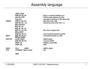
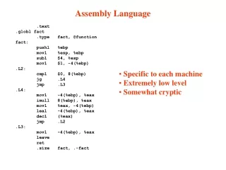
Example Assembly Code for 8051 *************************************************************************** * EMILY test1.asm program: Step through & increment local memory *************************************************************************** ORG $0000 BEGIN MOV R0,#0 Begin at bottom of internal RAM CLR A Zero initial value LOOP1 MOV [R0],A Write to internal RAM INC A Advance value INC R0 Advance register SJMP LOOP1 And continue *************************************************************************** * EMILY test3.asm program: Init data memory with value in A * Use the 'C'hange register command to set the initial value in A *************************************************************************** ORG $0800 BEGIN MOV DPTR,#0 Begin at zero MOV R2,#0 Low counter MOV R3,#0 High counter WRMEM MOVX [DPTR],A Write the value INC DPTR Advance DJNZ R2,WRMEM Loop 256 times DJNZ R3,WRMEM LOOP 256*256 times * Insert the ILLEGAL opcode to halt the simulation DB $A5 Halt Emily52 © Copyright 2004 Linden H. McClure, Ph.D. 7 Example .LST and .HEX Files Example .LST file (see test3.asm source file on previous slide) DUNFIELD 8051 ASSEMBLER: test3 PAGE: 1 0000 1 *************************************************************************** 0000 2 * EMILY test program: Init data memory with value in A 0000 3 * Use the 'C'hange register command to set the initial value in A 0000 4 *************************************************************************** 0800 5 ORG $0800 0800 90 00 00 6 BEGIN MOV DPTR,#0 0803 7A 00 7 MOV R2,#0 0805 7B 00 8 MOV R3,#0 0807 F0 9 WRMEM MOVX [DPTR],A 0808 A3 10 INC DPTR 0809 DA FC 11 DJNZ R2,WRMEM 080B DB FA 12 DJNZ R3,WRMEM 080D 13 * Insert the ILLEGAL opcode to halt the simulation 080D A5 14 DB $A5 Begin at zero Low counter High counter Write the value Advance Loop 256 times LOOP 256*256 times Halt emily Example test3.hex Motorola S-record hex file generated using: ASM51 test3.asm -F S11108009000007A007B00F0A3DAFCDBFAA57E S9030000FC Example test3.hex Intel hex file generated using: ASM51 test3.asm -FI :0E0800009000007A007B00F0A3DAFCDBFAA582 :00000001FF © Copyright 2004 Linden H. McClure, Ph.D. 8 4