Download
1 / 48
590 likes | 1.3k Views
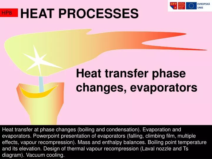
HEAT PROCESSES. HP8. Heat transfer phase changes, evaporators .

E N D
HEAT PROCESSES HP8 Heat transfer phase changes, evaporators Heat transfer at phase changes (boiling and condensation). Evaporation and evaporators. Powerpoint presentation of evaporators (falling, climbing film, multiple effects, vapour recompression). Mass and enthalpy balances. Boiling point temperature and its elevation. Design of thermal vapour recompression (Laval nozzle and Ts diagram). Vacuum cooling. Rudolf Žitný, Ústav procesní a zpracovatelské techniky ČVUT FS 2010
HEAT transfer condensation HP8 Dropwise condensation Film condensation Duchamp
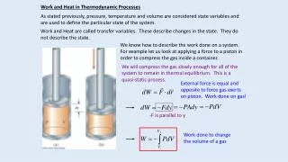
dx Mass flow rate of condensed steam x Tw Ts=Tw+T HEAT transfer film condensation HP8 Film condensation (Nusselt) The following analysis holds only for laminar films (Re<1800). It is usually sufficient, because majority of practical cases are laminar. Transversal parabolic velocity profile and balance of forces gravity Viscous force at wall Transversal linear temperature profile, heat and mass fluxes Thickness of film determines the heat transfer coefficient Gravity acting in the flow direction increases
HEAT transfer film condensation HP8 Enthalpy balancing of a condenser requires mean value of heat transfer The coefficient c is theoretically c=2/32=0.94 but experiments indicate that the actual value should be about 20% higher, therefore c=1.13 The increased film thickness decreases heat transfer c=0.725 Horizontal pipe Inclined wall N-rows of horizontal pipes See also M.N.Ozisik: Heat transfer, a basic approach, McGraw Hill, 1985
=liquid-solid HEAT transfer dropwise condensation HP8 Dropwise condensation (Schmidt)yields much higher heat transfer coefficients than the film condensation, however special smooth or hydrophobic coatings (large contact angle and very low surface energy of wall) of heat transfer surfaces must be provided. Gold plated surface Schmidt, E., Schurig, W. and Sellschop, W., Versucheuber die kondensation von wasserdampf und film undtropfenform. Tech. Mech. Thermodynamiks,Berlin,1930, 1, 53-63. Kakac S.: Boilers, evaporators, and condensers, Wiley 1991 D.W. Tanner, C.J. Potter, D. Pope, D. West: Heat transfer in dropwise condensation—Part I The effects of heat flux, steam velocity and non-condensable gas concentrationInternational Journal of Heat and Mass Transfer, Volume 8, Issue 3, March 1965, Pages 419-420, IN5, 421-426 M. ABU-ORABI: Modeling of heat transfer in dropwise condensation. Int. J. Heat Mass Transfer. Vol. 41, No. 1, pp. 81-87, 1998
HEAT transfer dropwise condensation HP8 H.M.Steinhagen: Smart surfaces for improved heat exchangers. Institute for Thermodynamics and thermal engineering, University of Stuttgart (presentation)
HEAT transfer boiling HP8 Pool boiling Flow boiling Tanguy
HEAT transfer pool boiling HP8 Nukyama curve (q-TSAT) see A.Bejan, A.Kraus: Heat transfer handbook. Willey 2003 Boiling crisis of the first kind
HEAT transfer pool boiling HP8 All parameters are related to liquid L Nucleate (pool) boiling Rohsenow (1952) uL - velocity of liquid surface Rohsenow W.M., Trans.ASME, Vol.74,pp.969-975 (1952) Exponent mis 0,7 for all liquids with the exception of water (m=0). The coefficientCLSdepends upon the combination surface-liquid (tables see Özisik (1985)) and for the most common combination steel-water CLS=0,013. Db is the Laplace constant characterizing diameter of bubble Interpretation of Db follows from the equilibrium of surface stress and buoyancy forces
HEAT transfer boiling onset HP8 The nucleate boiling (bubble boiling) regime is optimal for boilers or evaporators. How to specify its onset (or the level of superheating necessary for bubble formation on the heat transfer surface)? Balance of forces: overpressure – surface tension -surface tension Db diam. of a microcavity on heat transfer surface pb corresponds to saturated steam temperature at Tw=TSAT+TSAT p corresponds to saturated steam temperature TSAT Pressure difference pb –pcan be calculated from the temperature difference using Clausius Clapeyron equation Substituting into the balance of forces gives the final result
HEAT transfer boiling crisis HP8 Bubble flow regime ends at such a high intensity of evaporation that a more or less continuous layer of vapor is formed and creates a thermal barrier between the heat transfer surface and liquid. Critical heat flux Theoretical solution Zuber (1958) predictscoefficientc=0,131 , experimental data suggest little bit greater value c=0,18 , Rohsenow (1973). The relation for critical heat flux shows that the boiling crisis can be delayed by increasing pressure (and therefore densityG) or by acceleration pressing liquid layer towards the heat transfer surface (this is utilised in centrifugal evaporators). Theoretical prediction of boiling crisis is based upon stability analysis of a liquid layer (thickness H2) sitting above the light layer of vapor (H1). A small disturbance of initially planar interface increases area of interface (and therefore potential energy of surface tension W ) but at the same time decreases gravitational potential energy Wg. At the stability limit (neutral stability) the differential of the total potential energy is zero, This condition determines wavelength of disturbance causing disruption of continuous layer, and location of steam jets breaking through the liquid layer (it can be shown that the distance of these parallel jets is a multiple of the Laplace constant Db). Following stability analysis of these steam jets, based upon variation of potential energy of surface tension and kinetic energy, yields the previous expression for the critical heat flux.
HEAT transfer flow boiling HP8 Flow boiling in vertical pipes is characterized by gradual changes of flow regime and thevapor qualityx increase along the pipe Enthalpy of liquid at saturation temperature Annular flow (rising film) Vapor quality x<0 means subcooled liquid, vapor quality x=0 liquid at the beginning of evaporation, x=1 state when all liquid is evaporated and x>1 superheated steam. Slug flow Vapor quality is related to the Martinelli’s parameter (ratio of pressure drops corresponding to liquid and vapor) Nucleate boiling (bubbles), e.g. Rohsenow correlation Vapor quality and Martinelli’s parameter are used in most correlations for convective boiling heat transfer. Heat transfer by forced convection (e.g.Dittus Boelter)
HEAT transfer flow boiling HP8 The previous slide introduced two basic characteristics of two phase liquid- vapor flows: vapor qualityxand the Martinelli’s parameter X. Their relationship follows from the following reasoning: Gradient of pressure dp/dz for one phase flow is proportional to (see dArcy Weisbach equation) Exponent m=0.25 for low Re (Blasius), m=0.2 for high Reynolds numbers therefore and you can see that the corresponding exponent of Reynolds number in the correlation for pressure drop is m=0.2. It is obvious that the Martinelli’s parameter is a decreasing function of vapor quality (its value is infinity for liquid).
HEAT transfer flow boiling Chen HP8 Chen (1966) calculates the flow boiling heat transfer coefficient as the weighted sum of nucleate boiling b and the convective heat transfer in liquid film c Forster Zuber correlation for nucleate boiling (Chen’s concept was later modified by different correlations for nucleate regime, for example by Rohsenow correlation for pool boiling) Dittus Boelter correlation for convective heat transfer Chen J.C.: A correlation for boiling heat transfer to saturated fluids in convective flows. Industrial and Engineering Chemistry, Process design and development, Vol.5, no.3, (1966), pp.322-329
HEAT transfer flow boiling HP8 Chen’s method is probably the most frequently used, but it seems that his correlation overpredicts the effect of nucleation and many modifications were therefore suggested. These modifications replace the Forster Zuber pool boiling correlation by Rohsenow’s correlation and the suppression factor S and the convective enhancement factor F were correlated with other system variables Kandlikar S.G.: A general correlation for saturated two phase flow boiling heat transfer inside horizontal and vertical tubes. Journal of Heat Transfer, Vol.112, pp.219-228 (1990) Bennett D.L., Chen J.C.: Forced convective boiling in vertical tubes for saturated pure components and binary mixtures. AIChE J., Vol.26, pp.454-461 (1980) Shah (1976) introduced correlations based upon boiling number Bo, convection number Co (that replaces the Martinelli’s parameter) and Froude number Fr G is the mass flux, kg/m2s Viscosity ratio (see Martinelli’s parameter) seems to be unimportant Shah M.M.: A new correlation for heat transfer during boiling through pipes. ASHRAE Transactions, Vol.82, Part.II, pp.66-86 (1976)
HEAT transfer flow boiling HP8 Heat transfer correlations for the film condensation (Nusselt) and the flow boiling (Chen) are used in the followingExcel program designed for modeling of a climbed film evaporator (Kestner). Procedure: Tube is divided to short sections z. At each section (starting from bottom, feed input) are calculated: heat transfer coefficient at outer surface, heat flux, wall temperature, enthalpy change h, steam quality x, Martinelli’s parameter, and heat transfer coefficient using Chen’s method. Temperature dependence of all thermophysical properties is considered.
Evaporators HP8 Hopper
Evaporators HP8 Vapours (brüden) Saturated steam Evaporation of water (pool or flow boiling) feed Condenstation of saturated steam concentrate condensate Minton P.E.: Handbook of evaporation technology. Noyes Publ., New Jersey, 1986
Nomenclature What to do with vapor: • It can be condensed in a direct (spray), shell and tube or plate condensers • It can be used for heating the following evaporator unit (multiple effects evaporators) • It can be recompressed (by mechanical or thermo-compressor) and used for heating Evaporators HP8 Overall mass flow rate Mass balances mass flow rate of dissolved solid =cc(Tc-T0) Enthalpy balance dissolution heat
Evaporators HP8 External heater Forced circulation Natural circulation in short pipes Suppressed boiling (flash evaporation) High velocity in HE-low fouling Vogelbusch basket steam Robert’s POOL boiling prevails Long residence times vacuum vacuum vacuum steam condensate condensate condensate condensate Circulation pump Climbed film Falling film Wiped film Centrifugal Centrifugal forces promote dropwise condensation and increase critical heat flux Wiegand Müller Short residence times Only for low viscosities Viscous liquids Centritherm Kestner condensate Very small T
Evaporators HP8 Multistage evaporators (latent heat of vapor is used for the next effect heating) T1 T2 Counter current Low viscosity feed flows to the second stage at lower temperature (advantageous from point of view of heat transfer). T1>T2 therefore p1>p2 and it is necessary to use a pump T1 T2 Co current High viscosity concentrate flows to the second stage at lower temperature (suitable for heat sensitive products).
T1 T3 T2 Evaporators HP8 Number of effects is limited by range of temperatures (feed – condensate) T1 > T2 > T3 T1-T2 = THE + Tpch + Tp Temperature drop corresponding to pressure drop (frictional losses). Usually small ~ 10C Temperature difference on heat transfer surface (rising film >100C, falling film >40C) Physico chemical elevation of boiling point temperature (solution boils at elevated temperature). Can be large, depends on concentration
WI WII Tf,mf,f D,TS TI TII kISI kIISII mc,c m1,1 Mass balances Enthalpy balances 1st stage 2nd stage Evaporators HP8 Optimisation of a two effects evaporator What is given(it is assumed that the temperature TII is determined by condenser and is the same as the temperature of boiling solution in the second effect and the temperature of product): Tf mff – temperature, mass flowrate, mass fraction of feed TII c – temperature and mass fraction of product TS – temperature of steam What is to be calculated (9 variables): D,WI,WII– mass flowrates of steam and vapours m1,mc – mass flowrates of solution from the 1st and 2nd effect 1- mass fraction of solution after 1st stage TI –temperature of boiling solution in the 1st effect kISI, kIISII- heat transfer surfaces in both effects There exist only 8 equations for 9 parameters – one of them can be selected (for example boiling temperature in the first stage TI). This degree of freedom can be used for optimisation (for minimisation of the heat transfer surface or consumption of steam).
Evaporators HP8 Design of a two effect co-current evaporator can be implemented in Excel program Specify temperature of steam and feed Select temperature in the first effect TI Select substance and boiling point elevation CALC starts calculation Heat transfer surface will be result
Evaporators MVR HP8 MVR Mechanical Vapor Recompression Root’s blower A C D Condensate injection It would not be a good idea to use superheated steam for heating, because will be too small. Saturated steam and condensation is achieved by water injection BTU=1.054 kJ psi=6.9 kPa F=1.8C+32
2 1 5 Thermocompressor Evaporators TVR HP8 The most important equation is the momentum balance (mixing chamber) TVR Thermal Vapor Recompression Entrainment ratio fe(mass flowrate of entrained vaports to the mass florate of motive steam) follows from the momentum balance Power R.: Steam jet ejectors for the process industries. Mac Graw Hill, New York, 1994
Evaporators TVR HP8 Design diagram for TVR Motive steam presure Discharge pressure Suction pressure Power R.: Steam jet ejectors for the process industries. Mac Graw Hill, New York, 1994
2 1 5 Thermocompressor Evaporators TVR HP8 TVR Thermal Vapor Recompression Previous analysis determined only the entrainment ratio . To complete the TVR design it is necessary to calculate the mass flowrate of motive steam through the Laval nozzle (given inlet pressure). Laval nozzle is characterised by converging and diverging section and the mass flowrate depends only upon the cross section of throat (the smallest cross section S*) where the speed of sound is achieved. To determine the flow rate m1 as a function of S* and the inlet pressure p1 it is necessary to solve the complete velocity and pressure profiles along the Laval nozzle.
Mixing chamber Motive steam Laval nozzle Diffuser Suction Speed of sound Evaporators TVR HP8 Thermocompressor and Laval nozzle Unknown profiles along the Laval nozzle: p(x), v(x)-or density, T(x), u(x)-velocity, and h(x), together 5 unknowns Available equations: pv=RT - state equation pv=p1v1 - isoentropic flow (without friction) dh=-du2/2 - Bernoulli equation dh=cpdT By selecting any of the parameters, for example the pressure p, it is possible to calculate all other variables, for example the velocity u Ideal gas! v and dv is to be eliminated (expressed in terms of p) By integration we obtain St.Venant Wanzel equation
S* z Evaporators TVR HP8 Mass flowrate is independent of axial coordinate Introducing dimension pressure P*=p(z)/p1 the throat geometrical constraint (minimum cross section S) is Solution of this (algebraic) equation is and corresponding mass flowrate
H2O molecule riding inside a Laval nozzle HP8 Slow, nice, eliptic ride, clear view Approaching speed of sound, view is misty Collision with different pressure at outlet of Laval nozzle (wrong design, of course not by our students) Speed of sound and still accelerating, Molecule is blind, nothing is seen (only the rear mirror view is clear) S* z
p1 p Evaporator chamber operating at underpressure Evaporators St Venant Wanzel HP8 St Venant Wanzel equation is quite useful and not only for the Laval’s nozzle design. It is applied for example for estimation of an evaporator or a condenser leakage Leakage at sonic flow (choking). Mass flowrate is independent of vacuum level p. Mass flowrate through a gap with cross section S at subsonic flow
Foam separator Condenser cooker Heating jacket recommended for reading Condensate pump Vacuum pump Vacuum cooling LIQUIDS HP8 Evaporation is also used for rapid cooling of food materials. Material containing water (liquid solutions, but also porous solids like flowers, vegetables, meat) can be cooled down by evaporation of water at a decreased pressure. Assuming uniform temperature Tf(t) of the cooled material the enthalpy balance can be written as Mass flow rate of evaporated water M. Dostal, K. Petera: Vacuum cooling of liquids: mathematical model. Journal of Food Engineering 61 (2004) 533–539 conduction Convection (n is mass flux) There still exist controversial opinions concerning interpretation of thermal and mass transfer resistances at surface Area of liquid surface
Vacuum cooling WATER HP8 Technical realization is similar to vacuum evaporators, only without heating of evaporated liquid. Jet pumps (steam ejectors) are usually used. Example: GEA Wiegand GmbH, 2-stage steam jet cooling plant of compact design, cooling 44 m3/hr of water from 30 to 10 °C.
Spray cooling WATER HP8 Cooling ponds JETE
Vacuum cooling MEAT HP8 Relatively new vacuum cooling technology is applied also to porous solids, for example meat. The visualised cross-section of the cooked meat L. Wang, D.-W. Sun / International Journal of Refrigeration 25 (2002) 862–871 Mathematical modelling is usually based upon FK equation for heat transfer Heat flux Mass transport of vapour is expressed in terms of pressure P There exists doubt about this approach. It was objected that this model doesn’t recognize moving front between the boiling and diffusive regions. T.X. Jin, L. Xu / Energy Conversion and Management 47 (2006) 1830–1842 Evaporation rate Mass flux D.-W. Sun, L. Wang / Journal of Food Engineering 77 (2006) 379–385
Evaporatorspapers HP8 Bosch
Evaporatorspapers HP8 K.R. Morison, Q.A.G. Worth, N.P. O’dea Minimum Wetting and Distribution Rates in Falling Film EvaporatorsFood and Bioproducts Processing, Volume 84, Issue 4, December 2006, Pages 302-310 Falling film evaporators are used extensively in the food industry for their ability to process heat sensitive liquids. A coherent liquid film is required to maintain heat transfer efficiency and minimize fouling. It is likely that most evaporator fouling occurs after film breakdown as the substance within the evaporator dries out. The minimum flow rate required to maintain a film is known as the minimum wetting rate which is defined as the minimum mass flow rate per unit circumference. In this work, minimum wetting rates were determined in a 1 m long, 48 mm internal diameter, vertical, stainless steel tube. Water and aqueous solutions of glycerol, alcohol and calcium chloride were used. These substances were chosen so as to give a wide range of properties such as viscosity (0.5–39 mPa s), density (950–1410 kg m-3), surface tension (35–90 mN m-1) and contact angle (64–980). In a separate set of experiments, the minimum flow rate required to distribute liquid and completely wet the top of industrial evaporator tubes was measured using a range of sucrose solutions. The tube wetting results obtained fitted a dimensionless power law relationship well. Surface tension and contact angle had a strong influence on the wetting rate but viscosity and density were found to have very little effect. The minimum flow rates for distribution were found to nearly always exceed the minimum wetting rates showing that more attention needs to be given to distributor design. Almost the same result can be derived from the Weber number limit Nii S.et al: Membrane evaporators. Journal of membrane science, 201 (2002), 149-159
Evaporatorspapers HP8 Susumu Nii, R. Selwyn Jebson, E. L. Cussler Membrane evaporatorsJournal of Membrane Science, Volume 201, Issues 1-2, 31 May 2002, Pages 149-159 We have built and tested a flat-sheet membrane evaporator for removing water from dilute feed streams likemilk and orange juice. The energy for the water’s evaporation comes from steam channels next to the feed channels, so that the operation differs sharply from other forms of “membrane distillation”. The membrane evaporator retains flavors effectively. Because it has an overall vapor phase mass transfer coefficient of about 1 cm/s, it is only 68% efficient: only about 0.68 kg water is evaporated per kg steam condensed. This efficiency should be over 95% for a membrane which is 10 times more permeable.
Evaporatorspapers HP8 S. Sharma, G.P. Rangaiah, K.S. Cheah Multi-objective optimization using MS Excel with an application to design of a falling-film evaporator systemFood and Bioproducts Processing, Available online 9 February 2011 An Excel-based MOO (EMOO) program is developed based on the elitist non-dominated sorting genetic algorithm (NSGA-II) and tested on benchmark problems. It is then applied for MOO of design of a falling-film evaporator system, consisting of a pre-heater, evaporator, vapor condenser and steam jet ejector, for milk concentration. The EMOO program gave well-distributed Pareto-optimal solutions for the MOO problems tested. Design equations and results for two bi-objective optimization problems are presented and discussed.
Evaporatorspapers HP8 Tarif Ali Adib, Bertrand Heyd, Jean Vasseur: Experimental results and modeling of boiling heat transfer coefficients in falling film evaporator usable for evaporator designChemical Engineering and Processing: Process Intensification, Volume 48, Issue 4, April 2009, Pages 961-968 The aim of this paper is to describe the variation laws of the boiling heat transfer coefficient (h) versus the main process parameters, using a pilot scale falling film evaporator as found in many food industries. Sugar solutions at different concentrations are used as a model of Newtonian liquid food. The studied parameters affecting boiling heat transfer coefficient (h) in the falling film evaporator are: the dry matter concentration XDM (or Brix for sugar solution), the evaporating temperature (L) or pressure (P) taking into account the boiling point elevation (BPE), the heat flux or the temperature difference between the heated surface and boiling liquid temperature () and the specific mass flow rate per unit of perimeter length (). The nature of heated surface is kept constant (stainless steel) and the effect of the emitted vapor velocity is not taken into account in our study. The variations of h with or , are given for pure water and sugar solutions at different concentrations (10%, 30%, 50% and 70%), and interpreted in relation with the two boiling regimes (non-nucleate and nucleate). The transition between non-nucleate regime and nucleate regime has also been visually observed. The critical specific mass flow (cri) for water and sugar solution at dry matter concentration 50% has been studied. Variation of h as a function of temperature difference at P = 1010mbar and = 0.56 kg s−1 m−1 for pure water and sugar solution X = 10%, 30%, 50% and 70% DM.
Evaporatorspapers HP8 Xianchang Li, Ting Wang, Benjamin Day: Numerical analysis of the performance of a thermal ejector in a steam evaporatorApplied Thermal Engineering, Volume 30, Issues 17-18, December 2010, Pages 2708-2717 Ejectors have been widely used in many applications such as water desalination, steam turbine, refrigeration systems, and chemical plants. The advantage of an ejector system lies in its extremely reliable operation due to the complete absence of moving parts. However, the performance depends on a number of factors, among which the flow channel configuration/arrangement is critical. To improve the performance of an existing thermal compressor in a steam evaporator, a comprehensive study was conducted in this paper with a main focus on the sensitivity of performance to the geometric arrangement. Numerical simulation was employed to investigate the thermal-flow behavior. The performance is measured by the entrainment ratio, i.e., the secondary (suction) flow rate from a vapor plenum over the primary steam jet flow. It is observed that any downstream resistance will seriously impede the suction flow rate. In addition, the entrainment ratio is sensitive to the location of the jet exit, and there is an optimum location where the primary flow should be issued. A well-contoured diffuser can increase the entrainment ratio significantly. However, the size of suction opening to the plenum is less important, and a contoured annular passage to guide the entrained flow shows little effect on the overall performance. Based on the numerical results the steam entrainment rate of the best case in the confinement of the current study is approximately 430% of the jet flow rate, while some cases with mediocre design can only produce an entrainment of 24% of the primary jet flow. Fluent
EXAM HP8 Phase changes Evaporators Thermocompressors
dx Mass flow rate of condensed steam x Tw Ts=Tw+T What is important (at least for exam) HP8 Nusselt correlation for film condensation Rohsenow correlation for pool boiling Laplace constant Db is used as a characteristic dimension in Nu and Re
What is important (at least for exam) HP8 Vapours (brüden) Evaporation of water (pool or flow boiling). Use Rohsenow or Chen correlations Saturated steam feed Condensation of saturated steam (Nusselt correlation) concentrate Overall mass balance condensate Mass balance of solid Enthalpy balance
2 Mixing chamber Motive steam Laval nozzle 1 Diffuser 5 Suction Thermocompressor Speed of sound What is important (at least for exam) HP8 Recompression of vapours by thermo-compressor (that is driven by Laval nozzle) Laval nozzle Supersonic flow for pressure ratio Mass flowrate is independent of outlet pressure at supersonic flow