Download
1 / 14
140 likes | 552 Views
CM 197 Mechanics of Materials Chap 13: Shear Forces and Bending Moments in Beams. Professor Joe Greene CSU, CHICO Reference: Statics and Strength of Materials , 2 nd ed., Fa-Hwa Cheng, Glencoe/McGraw Hill, Westerville, OH (1997) . CM 197. Chap 13: Shear Forces and Bending Moments. Topics

E N D
CM 197Mechanics of Materials Chap 13: Shear Forces and Bending Moments in Beams Professor Joe Greene CSU, CHICO Reference: Statics and Strength of Materials, 2nd ed., Fa-Hwa Cheng, Glencoe/McGraw Hill, Westerville, OH (1997) CM 197
Chap 13: Shear Forces and Bending Moments • Topics • Introduction • Types of Beams • Types of Loading • Beam Reactions • Shear Force and Bending Moment in Beams • Shear Force and Bending Moment Diagrams • Relationships Among Load, Shear, and Moment • Sketching Shear and Moment Diagrams Using Relationships • Shear and Moment Formulas
Introduction Plane of symmetry • Beams are members that carry transverse loads and are subjected to bending. • Any structural member subjected to bending may be referred to as a beam. • Shafts, girders, stringers, floor beams, joists, etc. • Objective of chapter • Determine the internal forces at various sections along a beam. • Review Types of beams and supports. • Calculation of beam sections. • Calculation of internal forces (shear and moments) in the beam. • Produce graphical representations of shear and bending moments. • Assumptions • Beams are straight and of uniform cross sections that possess a vertical plane of symmetry. Fig 13-1 • Horizontal positions • Subjected to forces applied in the vertical plane of symmetry.
Types of Supports for Beams R Rx Ry Rx M Ry • Supports • Roller supports • Roller or link support resists motion of the beam only along the direction perpendicular to the plane of the support (along axis) • Reaction at roller support acts along the known direction. Fig 13-2 • Have one unknown Reaction force, R • Hinge supports • Resists motion of the beam at the support in any direction on the plane of loading. • Have two unknown Reaction forces- Rx and Ry • Fixed supports • Beam is built into wall or column. • End of beam is fixed and doesn’t move. • Have two unknown Reaction forces, Rx and Ry, and one unknown Moment, M
Types of Beams • Beams • Simple Beam (Statically Determinate- 3 unknowns) • Beam supported at its end with a hinge and a roller • Overhanging Beam (Statically Determinate- 3 unknowns) • Simple supported beam with an overhang from one or both ends • Cantilever Beam (Statically Determinate- 3 unknowns) • Beam that is fixed at one end and free at the other • Propped cantilever beam (Statically Indeterminate >3 unknowns) • Beam that is fixed at one end and simply supported at the other. • Fixed Beam (Statically Indeterminate >3 unknowns) • Beam with both ends are fixed to supports • Continuous Beam (Statically Indeterminate >3 unknowns) • Beam is supported on a hinge and two or more roller supports
Types of Loading • Loading • Concentrated Loads • Load is applied at a specific point on the beam and is considered a discrete force acting at the point. • Example, weight fastened to a beam by a cable that applies a concentrated load. • Uniform Loads • Load is distributes over a part or the entire length of the beam. • Load is force per unit length of beam (lb/ft or N/m) • Replaced with equivalent force = uniform load times length of beam • Example, weight of beam. • Linearly Varying Loads • Load is distributed with a uniform variation of intensity. • Occurs on a vertical or inclined wall due to liquid pressure. • Load changes along the length of the beam.
Beam Reactions • Beam Reactions • Review of Chapter 3 • Procedure • Write three independent equilibrium equations to solve for the three unknowns. • Three equations could be combinations of force-component or moment equations, as long as they are independent of each other. • This chapter assume no horizontal forces. • Thus reaction force in horizontal direction is zero. • Assume, sum of forces in x direction is 0, thus the horizontal reaction is 0. • Example, 13-1 • Example, 13-2
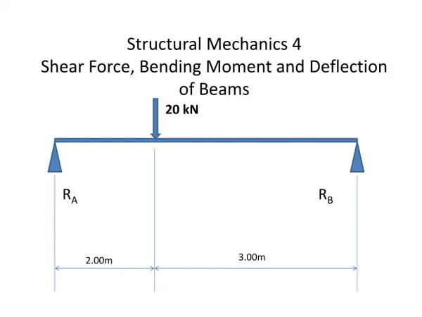
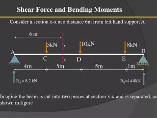
Shear Force & Bending Moment in Beams 100 lb 200 lb Rx 1 ft 3 ft Ry R 10 ft • Shear Force and Bending Moment • Developed in a beam to resist the external forces and to maintain equilibrium. • Figure 13-7 • Beam is 10 ft long with roller support on the right and hinge support on left. • Beam is subjected to two concentrated loads. • Results • For cross section at 3 feet from the left, the forces and moments need to be balanced. • Balance the forces and moments at each section • Normal forces: Rx = 0; Ry =150 pounds; • Shear force: V = 150 – 100 = 50 lbs; Moment is acting clockwise and = 3*150 – 100*2 = 250lb-ft; • Internal resisting moment moment has to be equal and opposite of moment and acting opposite direction. M = 250ft-lb counterclockwise. • For results for cross section from the right, the forces and moments are calculated in the same manner.
Beam Sign Conventions • Positive Shear • Shear force at a section is positive if the external forces on the beam produce a shear effect that ends to cause the left side of the section to move up relative to the right side. Fig 13-8a • Positive Moment • Bending moment at a section is positive if external forces on the beam produce a bending effect that causes the beam to concave upward at the section. Fig 13-8b • Positive internal shear force, V, at a given section of a beam viewed from both directions is shown in Fig 13-8c. • Positive internal moment M at a given section of a beam viewed from both directions is shown in Fig 13-8d. • Rule 1 for finding shear forces • Internal shear force at any section of a beam is equal to the algebraic sum of the external forces on either segment separated by the section. • From the left of beam: upward force as positive • From the right of the beam: downward force as positive • Rule 2 for finding bending moments • Internal bending moment at any section of a beam is equal to the algebraic sum of the moments about a section due to external forces. • From either side: moment due to upward force as positive • Example, 13-1 and Example, 13-2
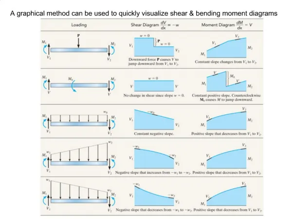
Shear Force and Moment Diagrams • Shear force and bending moment diagrams depict the variation of shear force and bending moment along a beam. • Help visualize the shear forces and bending moments along beam • Construct diagram • Ordinate (y-axis) values are from balance of forces and moments. • Compute reaction forces and moment couples. • Plot values of the shear just below the free body diagram on the y-axis with positive values above the baseline and negative values below the baseline. • Plot values of moments just below the shear diagram on same x-axis scale with positive values above the baseline and negative values below the baseline. • Important aspects of diagrams • For concentrated loads • The shear diagram has a horizontal line between the loads • The moment diagram has a line with constant slope • For distributed loads • The shear diagram has a line with a constant slope. • The moment diagram has a curved line between moment points. • If the shear diagram crosses the horizontal line (at zero shear) then it has a maximum or minimum moment at that point. • Example 13-5
Relationships among Load, Shear, and Moment • Certain relationships exist among the loading diagram, shear diagram and moment diagram. • Assume incremental element of a beam. • Relationships between Load and Shear • For a distributed load, w, applied to a beam, • The slope of the shear diagram (rate of change of the shear force per unit length) at any section is equal to the load intensity at that section. • The shear force at a section is equal to the shear force at the previous section plus the total load between the two sections. • Shear force at the section immediately to the right of a concentrated load is equal to the shear force immediately to the left plus the load. • Shear force has an abrupt change at the concentrated load, upward = + • Relationship between shear and moment • Moment at a section is equal to the moment at the previous section plus the area under the shear diagram between the two sections.
Using Relationships of Diagrams • Loading Diagram or free body diagram • Show all applied forces and reactions on beam plus dimensions • Never replace a distributed load with an equivalent concentrated load • Shear diagram procedure • Draw shear diagram directly below the loading diagram. • Horizontal line is drawn at proper location below loading diagram. • Draw vertical lines from controlling sections for supports and loads. • Start at left end and compute shear at controlling sections using Eqn 13-5 VB = VA + LoadB-A • Note: Section with concentrated force is applied, shear force diagram has an abrupt change at concentrated load location. • Plot points on shear diagram using forces at each load. • Connect points • Note: Sections with distributed loads have a sloping line between them. • Note: Slope of line is the intensity of the load. Concentrated loads have slope = 0
Using Relationships of Diagrams • Moment diagram procedure • Draw moment diagram directly below the shear diagram. • Horizontal line is drawn at proper location below loading diagram. • Draw vertical lines from controlling sections for supports and loads • Calculate areas from shear diagram for each section. • Note: moments at free end or ends of a simple beam are always = 0. • Start at the left end and compute the moments using Eqn 13-7, MB = MA + AreaB-A • Plot points on moment diagram using previous moments and areas at each section • Connect points with straight lines (for concentrated loads) or curves (for distributed loads) • Note: Maximum or minimum of moment occurs at the location where the shear is = 0 or where the shear changes sign. • Example, 13-6, 13-7, 13-8, 13-9
Shear and Moment Formulas • From previous section, shear force and bending moment diagram can be plotted for some simple but typical loading conditions. • Table 13-1 • Procedure • Match the loading conditions to one or more loading examples in Table 13-1 • Get the loading solutions from the example and use it in problem for • Reaction forces, Maximum shear, maximum moments, etc. • Method of superposition • Effect of each load is computed separately and the then combined effect is added algebraically. • Example, 13-10, 13-11