Download
1 / 30
320 likes | 999 Views
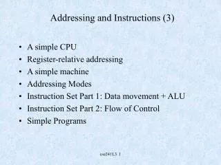
Addressing and Instructions (3). A simple CPU Register-relative addressing A simple machine Addressing Modes Instruction Set Part 1: Data movement + ALU Instruction Set Part 2: Flow of Control Simple Programs. A simple cpu. Throughout the following discussions, we choose as a model

E N D
Addressing and Instructions (3) • A simple CPU • Register-relative addressing • A simple machine • Addressing Modes • Instruction Set Part 1: Data movement + ALU • Instruction Set Part 2: Flow of Control • Simple Programs cse241L3 1
A simple cpu Throughout the following discussions, we choose as a model a simple CPU --N general purpose registers (N=8,16) --simple ALU --simple instruction set --simple addressing repertoire Note: modern processors are considerably more complex than the models given here. These models are illustrative only. cse241L3 2
A simple cpu (grossly oversimplified) PC R0 R1 IR Control Logic R7 ALU MAR MDR cse241L3 3
General Purpose Registers General purpose registers are CPU (Data Path) registers which --provide fast, usually temporary storage of data --are small in number (16,32,64) --have no control function (compare PC, MAR, IR, MDR) --are functionally identical (i.e., there is usually no difference between Rj and Rk -- but note that this is not always true) --we will designate these as R0,..,R7,...,R15,....,R31 cse241L3 4
Operand Address Representation • Consider a 32-bit machine. Suppose we wish to represent the instruction • clr a --meaning “clear the contents of memory location a” • How would we represent this instruction? • suppose we encode such instructions in one word • we have 32 bits per word • thus memory addresses can be at most 32 bits wide • but we have to encode the instruction itself • this will occupy some bits in the word cse241L3 5
Sample Instruction Format 32 bits K bits 32-K bits Allocating K bits to encode the instruction would let us have 2K instructions (more on this later) BUT The operand field has 32-K bits, NOT 32 bits Since the total address space of this machine is 232, there are some addresses which could not be represented in the 32-K bits which remain in the instruction (under direct addressing) cse241L3 6
Sample Instruction Format (cont) 8 bits 24 bits upper limit of memory that can be addressed by 24 bits Suppose K = 8; then the operand field of the instruction occupies 24 bits; thus it can represent the addresses 0 to 224-1; but it cannot represent the addresses (numbers) 224 to 232-1 Memory cse241L3 7
Indexing Indexing can solve this problem; provided the index register is 32 bits long, then all of memory can be accessed via an index register. The use of an offset in the instruction simply provides greater flexibility:- offset + Index Register 32 bits The 32-bit index register can store all values of the address range 0 to 232-1; thus, all of memory can be addressed. Later we will see the situation shown here being reversed. Memory cse241L3 8
Register Addresses • Like memory, registers can also have addresses • These addresses are used internally by the CPU to distinguish registers • Since there are fewer registers compared to the address space of the machine, far fewer bits are required to identify a register • Suppose we have a machine with 8 General Purpose Registers (R0 -- R7) -- thus, we require 3 bits to represent the register addresses cse241L3 9
Register-Relative Addressing • We can use registers as the primary vehicle for developing operand addresses • This is a more “natural” addressing strategy than the strategies previously described • Operands are stored in registers or memory • Register addresses are specified directly in instructions • Memory addresses are usually specified via the registers cse241L3 10
Typical Register-Relative Addressing Modes • NB: the terminology used here can vary from author to author • Register Direct • the address in the instruction is the address of the register which contains the operand • Register Indirect • the address in the instruction is the address of the register whose contents are the address of the operand (in memory) • Deferred • the address in the instruction is the address of the register whose contents are the address of the memory location whose contents are the address of the memory location whose contents are the operand cse241L3 11
Register Direct Value in operand field = 3 R3 --operand is the contents of R3 If we have N GPRs, we require ceil( log2 N) bits to represent the register address in an instruction. (Thus 8 registers require 3 bits). A register operand is identified in the instruction by the value in a particular field of the instruction (see later). cse241L3 12
Register Indirect Value in operand field = 3 R3 --contents of R3 is the address in memory of the operand 512 512 Operand is located at memory location 512 cse241L3 13
Register Deferred Value in operand field = 3 R3 --contents of R3 is the address in memory of the address of operand 512 Operand address is located at memory location 512 512 1024 1024 Operand is located at 1024 cse241L3 14
So, what do real addressing modes look like? • “Real addressing modes” depend on the machine. Some machines have complex addressing modes, some quite trivial addressing modes • The sample below is from an older (but in many ways prototypical) machine -- the PDP-11 • Refer to the text for PowerPC and Pentium • See the sparc emulator later • Refer to CSE240 for Pentium cse241L3 15
Why the PDP-11 • The PDP-11 is an antique • but • it had a variety of addressing modes • some of these modes are (relatively) complex • so it worth seeing these modes • However • you will see more modern addressing modes in the sparc later • compare another system (Pentium) to the PDP11 cse241L3 16
Addressing in the PDP-11 • The PDP-11 implemented 8 addressing modes (and had 8 registers) • The PDP-11 was a 16-bit machine (1 word = 2 bytes; see autoincrement and autodecrement below) • Register-relative addressing is used (instructions basically contained register addresses, but see later) • Consider how the PDP-11 implemented:- • direct addressing • indirect addressing • indexed addressing • immediate addressing cse241L3 17
Addressing Modes based on the PDP-11 cse241L3 18
Contents of R4 points address of address of operand Operand is in location 380 Autoincrement Indirect (deferred) 128 R4 128 128 + 2 = 130 380 R4 is incremented (by 2 here) to point now to 130 cse241L3 19
Instruction indicates a register to be used as index register + contents of register are added to 2’s complement offset stored in the word following the instruction; this is the address of the address of the operand Operand retrieved from memory Indexed Indirect instruction cse241L3 20
The role of the PC in register-relative addressing • The PC plays a significant role in register-relative addressing • Consider the addressing modes 3 and 7 previously (indexed and indexed indirect) • Suppose we choose the PC as the index register • What are the benefits of doing this? (See later) cse241L3 21
Instruction Formats based on the PDP-11 • We have the following: • each word in the PDP-11 occupies 16 bits • there are 8 registers • there are 8 addressing modes • the PDP-11 has three kinds of instructions (classified by operand count) • 2 operand instructions • 1 operand instructions • 0 operand instructions • therefore, we should be able to deduce the instruction formats quite easily cse241L3 22
Representing Operands (based on PDP-11) If we have 8 registers and 8 addressing modes, and if each addressing mode can apply to each register, then there are 64 total register/addressing mode combinations, requiring 6 bits to represent them:- 6 bit operand field 3 bits 3 bits to represent to represent the addressing the register mode cse241L3 23
2- and 1- operand instructions 2-operand instructions require a source and a destination operand; since each operand occupies 6 bits (12 bits total), there are 4 bits available to store the OPCODE, the binary value which identifies the instruction Opcode Source Operand Destination Operand 4 bits 6 bits (3+3) 6 bits (3+3) 1-operand instructions require just a source operand; since this operand occupies 6 bits , there are 10 bits available to store the OPCODE, the binary value which identifies the instruction. Opcode Operand 10 bits 6 bits (3+3) cse241L3 24
0-operand instructions and counting instructions A 0-operand instruction has no operands; therefore all 16 bits are available for use by the opcode. So we have the following:- 2-operand instructions 4 bit opcode field 1-operand instructions 10 bit opcode field 0-operand instructions 16 bit opcode field Seems quite straightforward:- there can be 16 2-operand instructions 1024 1-operand instructions 65536 0-operand instructions But of course this is not correct. why not? cse241L3 25
Counting Instructions The three instruction formats are shown schematically above. Consider the binary pattern 0110111010101110 Does it represent a 2-operand instruction, a 1-operand instruction or a 0-operand instruction? Consider the 2-operand instructions. Recall that 4 bits are used to specify the opcode (the binary representation of the instruction). Now suppose that every operand pair can be used by every 2-operand instruction. There are 64 different possible source operands There are 64 different possible destination operands Thus there are 64x64 = 4096 different possible operand pairs If there were 16 possible 2-operand instructions, there would therefore be ? different opcode and operand pair possibilities? There would be 16x4096 = 65536 such opcode/operand pair groupings cse241L3 26
Counting Instructions Recap: if we had 16 possible 2-operand instructions, and all operand pairs were permissible, we would have 65536 different instruction/operand(pair) combinations. But in a 16-bit word, there are only 65536 possible binary patterns. So there is no room left to encode the 1-operand or the 0-operand instructions. So, not every possible 2-operand opcode can represent an instruction; at least one “opcode” must be used to say: I am not a 2-operand instruction; I am a 1-operand or 0-operand instruction. Suppose we choose “1111” to identify this. Then every 1- and 0-operand instruction begins with the 4 bit sequence “1111” cse241L3 27
Typical Instructions 2-operand instructions mov src, dst dst = src add src, dst dst = src+dst sub src,dst dst = dst-src and src, dst dst = src&dst cmp src,dst compare src and dst mul src, dst dst = src*dst 1-operand instructions clr dst dst = 0 inc dst dst = dst+1 dec dst dst = dst-1 neg dst dst = -dst cmp dst dst = ~dst Flow of control* jmp L jump to L beq L branch to L if last result = 0 bgt L branch to L if last result > 0 blt L branch to L if last result < 0 bge L branch to L if last result >=0 ble L branch to L if last result <=0 * detailed later cse241L3 28
Assembler Syntax Assembler syntax provides a human-readable version of the binary patterns which correspond to the instructions. The syntax is:- 2-op: <label> operation src,dst 1-op: <label> operation dst 0-op: <label> operation where <label> is an optional position marker used by the assembler to keep track of the location (in memory) of that instruction Instructions are written one per line, and they are executed sequentially unless a branch condition occurs. An assembler converts the human-readable syntax to machine-readable binary patterns. (See Assignments 1 and 2). cse241L3 29
Addressing Mode Syntax The addressing mode syntax of the PDP-11 is as follows:- Mode Name Syntax 0 Register Rn 1 Autoincrement Rn+ 2 Autodecrement -Rn 3 Index X(Rn) 4 Register Indirect @Rn 5 Autoincrement Indirect @Rn+ 6 Autodecrement Indirect @-Rn 7 Index Indirect @X(Rn) Thus, mov @-R5,R3+ would be interpreted as: the source operand is autodecrement indirect using register R5 the dest. operand is autoincrement using register R3 cse241L3 30