Download

1 / 1
20 likes | 227 Views
1 University of Michigan – Ann Arbor 2 Princeton Plasma Physics Laboratory. 1 S. Wagner, 2 C. Priniski, 2 C. Gentile 2 R. Parsells, 2 T. Kozub, 2 T. Dodson. Analysis of a Helium Brayton Power Cycle for a Direct-Drive IFE Power Reactor.

E N D
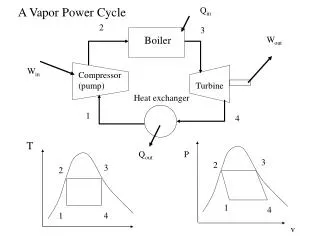
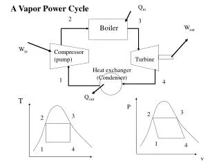
1 University of Michigan – Ann Arbor 2 Princeton Plasma Physics Laboratory 1S. Wagner, 2C. Priniski, 2C. Gentile 2R. Parsells, 2T. Kozub, 2T. Dodson Analysis of a Helium Brayton Power Cycle for a Direct-Drive IFE Power Reactor 19th High Average Power Laser Program Workshop, October 22nd-23rd, 2008, Madison, WI Motivation A direct-drive inertial fusion energy (IFE) power reactor is a promising new energy source for the future. To be economically competitive, the most efficient method of power conversion must be utilized to offset higher capital costs. Traditional power conversion cycles are limited by high IFE reactor temperatures, materials considerations, and radiological safety. A closed-cycle helium Brayton cycle is an economical solution that is very efficient at high temperatures and has advantageous properties for operation in an IFE environment. Helium has the second highest specific heat (below hydrogen) thus requiring a lower mass flow rate to transfer the same amount of heat. Also, proposed reactor designs, most notably the High Average Power Laser (HAPL) program, use a primary molten salt coolant loop for the dual purpose of breeding tritium (H3) as well as heat transfer; using helium is advantageous in this situation because it is the most chemically inert of all elements and will not interact with any molten salt components in case of failure. Helium is also easily purified if any tritium were to permeate the heat exchanger. The closed-cycle gas turbine (CCGT) has been historically proven as an effective power conversion cycle. Extensive research and development has been done in both experimental and industrial settings, making the cycle economically feasible, empirically reliable, and very efficient. Engineering Considerations From an engineering standpoint, the helium closed-cycle gas turbine (CCGT) has many challenges to address before operation in an IFE setting. The major in-cycle components: gas turbines, compressors, recuperator, and heat exchangers all need to be adequate for the operational environment. Pressurized helium represents a unique challenge for a CCGT as well as very high inlet temperatures (~800oC). The table below represents engineering and material considerations for all of the CCGT in-cycle components as well as proposed solutions. Figure 2: Pre-conceptual design of the High Average Power Laser (HAPL) IFE power reactor Figure 3: General Atomics Gas Turbine Modular Helium Reactor, a CCGT nuclear power plant System Design Considerations Operation of a helium closed-cycle gas turbine (CCGT) in an IFE environment requires design considerations for safety, reliability, and operational efficiency. For efficiency, a split-shaft design (the turbine operating the compressors has a split shaft from the compressors) should be strongly considered as it offers optimization of compressor speeds, however, requires fast-acting control systems in case of rapid load fluctuations. The use of intercoolers to decrease compressor work is also an efficiency gain that could be employed. In terms of reliability, the in-reactor components will be designed to withstand at least a year of operation without maintenance inside the reactor containment building; however, the CCGT should be located outside of the containment vessel because of maintenance considerations for the turbocompressor, generators, and integrated safety valves, thus dictating the use of an intermediate heat cycle to transport the heat out of the main containment vessel. Tin – temperature out of the IHX ηC / ηT – adiabatic efficiencies of compressor/turbine Tmin – minimum cycle temperature ΔP/Pout – cycle pressure drop Πc – overall compression ratio εrec – recuperator effectiveness rp – individual component compression ratio γ – ratio of the specific heats (Cp/Cv) Figure 4: Silicon infused Carbon-Carbon Intermediate Heat Exchanger Figure 5: Plate-Fin Recuperator Geometry R. Schleicher, R. Raffray, C. Wong (2001) Previous analysis done by Schleicher et al. (2001) concluded that a gross cycle efficiency of 51% could be attained using design specifications of closed-cycle helium turbines previously designed and operated, shown in the above table. The equations for the cycle gross efficiency, η cycle, is illustrated above and is dependent on those key parameters. It was estimated that within 10-20 years, technology would develop to improve those parameters to the values listed in the third column of the table, further increasing the cycle gross efficiency to 64%. The graph above shows the sensitivity of the cycle gross efficiency to the various parameters. It is seen that increasing the inlet temperature has the greatest effect on the efficiency. This is a problem because the inlet temperature is not a specification controlled by the power conversion cycle, but by the reactor design and any intermediate heat exchangers. Thus, any major efficiency improvements are greatly determined by the reactor design, not the in-cycle technology. Conclusions A direct-drive inertial fusion energy (IFE) power reactor is a very attractive future power source. In order to keep the reactor economically feasible, an equally advanced power conversion cycle must be utilized to maximize the plant efficiency while designing for the challenges of operating in a nuclear fusion environment. The closed-cycle helium Brayton cycle offers an economically competitive cycle that is very advantageous for a direct-drive IFE design requirement. Figure 1: Flow Diagram of Closed-Cycle Helium Brayton Cycle Support is provided by the U.S. DOE Contract No. DE-AC0276CH03073 and the 2008 Science Undergraduate Laboratory Internship, and the HAPL program.