Download
1 / 12
120 likes | 124 Views
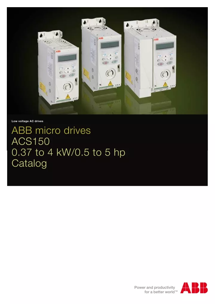
ABB ACS150 - micro drive:Take smooth performance to the next level with the wide power range and functionality of ACS150. Available in both single and three phase supplies. Many functions are standard, such as PID control, a built-in brake chopper and EMC filter. An optional FlashDrop drive configuration tool makes configuring unpowered drives quick and easy. <br>For More Information visit on our website:- www.instronline.com<br>Our E-mail Address:-info@instronline.com <br>

E N D
Low voltage AC drives ABB micro drives ACS150 0.37 to 4 kW/0.5 to 5 hp Catalog
Introduction to ACS150 ABB micro drives ABB micro drives are designed to be incorporated into a wide variety of machines such as mixers, conveyors, fans or pumps or anywhere where a fixed speed motor needs to go variable speed motor. Highlights – Worldwide availability through logistical distributors – User-friendly LCD control panel and integrated potentiometer – Flexible mounting alternatives – PID control – Integrated EMC filter – Built-in brake chopper – FlashDrop tool for fast drive commissioning The ABB micro drives meet the requirements of OEMs, machinery builders and panel builders. These drives are widely available through the ABB distribution network. The drives are easy to select and provide a range of built-in features as standard including PID control, brake chopper, fixed keypad and speed control potentiometer. Feature Advantage Benefit Worldwide availability and service Drives are available worldwide and permanently stocked in four regions. Dedicated global service and support network that is one of the widest in the industry. Fast and reliable delivery with dedicated support to any country in the world. User-friendly LCD control panel and integrated potentiometer Clear alphanumeric display. Easy setup and use. Time savings due to quick setup and simple configuration. Flexible mounting alternatives Screw or DIN rail mounting, sideways or side-by-side. One drive type can be used in various designs, saving installation costs and time. Integrated EMC filter High electromagnetic compatibility. Low EMC emissions in selected environments. Built-in brake chopper as standard No need for an external brake chopper. Space savings, reduced installation cost. FlashDrop tool Faster and easier drive setup and commissioning for volume manufacturing and maintenance. The FlashDrop tool enables both downloading and uploading drive parameters. Fast, safe and trouble-free parameter setting without the need to power-up the drive. Patented. PID control Varies the drive’s performance according to the need of the application. Enhances production output, stability and accuracy. Coated boards Board coating protects the electronics from hazards including static discharge and airborne contaminates, including moisture. Reduces maintenance due to good protection of electronics components. 2 ABB micro drives ACS150 | Catalog
Easily integrated drives for a wide range of applications ABB micro drives bring speed control benefits to a wide variety of applications. A heat pump system consists of an indoor unit with fan and an outdoor unit with a compressor and a blower. The heat pump cools indoor environment by gathering heat from the air, and transferring the heat outside. The outdoor unit uses the compressor and the blower to dissipate the heat. The cooled air is blown indoors by fans located in the indoor unit. Drive allows the user to variably control the cooling power based on customer request. AC drives optimizes systems’ energy efficiency and smoothens system operation. In mixing applications the drive provides high starting torque which benefi ts the start of the mixing operation. The silent operation mode adjusts the switching frequency of the drive to a higher level after the high-torque start, resulting in lower audible noise. The FlashDrop tool provides a quick and safe way to confi gure multiple drives for identical mixer applications. In conveyors the belt speed can be controlled using a drive and a motor. Production lines often have multiple stages, including conveyors, which need to be efficiently linked with each other to provide high production output. A drive provides smooth start and stop of the conveyor, thereby reducing mechanical stress and lowering maintenance costs. Fans are used for process cooling and ventilation in industrial, commercial and domestic environments. Using a drive to control air fl ow enables energy savings compared to mechanical fl ow control methods. An ABB drive has integrated PID control which provides optimal air flow by adjusting the fan speed based on a given reference value. Compact size and various mounting methods enable flexible system design. Catalog | ABB micro drives ACS150 3
Ratings, types and dimensions Type designation In column 4 on the right is the unique reference number that clearly indentifies your drive by power rating and frame size. Once you have selected the type designation, the frame size (column 5) can be used to determine the drives dimensions, shown below. Ratings PN kW 1-phase AC supply, 200 to 240 V 0.37 0.5 0.75 1 1.1 1.5 1.5 2 2.2 3 3-phase AC supply, 200 to 240 V 0.37 0.5 0.55 0.75 0.75 1 1.1 1.5 1.5 2 2.2 3 3-phase AC supply, 380 to 480 V 0.37 0.5 0.55 0.75 0.75 1 1.1 1.5 1.5 2 2.2 3 3 4 4 5 Type designation Frame size PN hp I2N A 2.4 4.7 6.7 7.5 9.8 ACS150-01X-02A4-2 ACS150-01X-04A7-2 ACS150-01X-06A7-2 ACS150-01X-07A5-2 ACS150-01X-09A8-2 R0 R1 R1 R2 R2 Voltages ACS150 is available in two voltage ranges: 2.4 3.5 4.7 6.7 7.5 9.8 ACS150-03X-02A4-2 ACS150-03X-03A5-2 ACS150-03X-04A7-2 ACS150-03X-06A7-2 ACS150-03X-07A5-2 ACS150-03X-09A8-2 R0 R0 R1 R1 R1 R2 2 = 200 to 240 V 4 = 380 to 480 V Insert either “2” or “4”, depending on your chosen voltage, into the type designation shown on the right. Construction “01X” and “03X” within the type designation varies depending on the drive phase and EMC filtering. Choose below the one you need. 1.2 1.9 2.4 3.3 4.1 5.6 7.3 8.8 ACS150-03X-01A2-4 ACS150-03X-01A9-4 ACS150-03X-02A4-4 ACS150-03X-03A3-4 ACS150-03X-04A1-4 ACS150-03X-05A6-4 ACS150-03X-07A3-4 ACS150-03X-08A8-4 R0 R0 R1 R1 R1 R1 R1 R1 01 = 1-phase 03 = 3-phase E = EMC filter connected, 50 Hz frequency U = EMC filter disconnected, 60 Hz frequency (In case the filter is required it can easily be connected.) X within the type code stands for E or U. Cabinet-mounted drives (UL open) Frame IP20 UL open size H1 mm R0 169 R1 169 R2 169 H2 mm 202 202 202 H3 mm 239 239 239 W mm 70 70 105 D mm 142 142 142 Weight kg 1.1 1.3 1.5 H1 H2 H3 H1 = Height without fastenings and clamping plate. H2 = Height with fastenings but without clamping plate. H3 = Height with fastenings and clamping plate. W = Width D = Depth D W Wall-mounted drives (NEMA 1) Frame NEMA 1 size H4 mm R0 257 R1 257 R2 257 H5 mm 280 280 282 W mm 70 70 105 D mm 142 142 142 Weight kg 1.5 1.7 1.9 H4 H5 H4 = Height with fastenings and NEMA 1 connection box. H5 = Height with fastenings, NEMA 1 connection box and hood. W = Width D = Depth D W 4 ABB micro drives ACS150 | Catalog
Technical data Mains connection Programmable control connections 1-phase, 200 to 240 V ± 10% 0.37 to 2.2 kW (0.5 to 3 hp) 3-phase, 200 to 240 V ± 10% 0.37 to 2.2 kW (0.5 to 3 hp) 3-phase, 380 to 480 V ± 10% 0.37 to 4 kW (0.5 to 5 hp) 48 to 63 Hz Voltage and power range One analog input Voltage signal Current signal Potentiometer reference value Resolution Accuracy Auxiliary voltage Five digital inputs 0 (2) to 10 V, Rin > 312 kΩ 0 (4) to 20 mA, Rin = 100 Ω 10 V ± 1% max. 10 mA, R < 10 kΩ 0.1% ± 2% 24 V DC ± 10%, max. 200 mA 12 to 24 V DC with internal or external supply, PNP and NPN, pulse train 0 to 16 kHz 2.4 kΩ Frequency Motor connection 3-phase, from 0 to Usupply 0 to 500 Hz Rated output current I2N Voltage Frequency Continuous loading capability (constant torque at a max. ambient temperature of 40 ºC) Overload capability (at a max. ambient temperature of 40 ºC) Switching frequency Default Selectable Acceleration time Deceleration time Braking Motor control method Input impedance One relay output Type Maximum switching voltage Maximum switching current Maximum continuous current NO + NC 250 V AC/30 V DC 0.5 A/30 V DC; 5 A/230 V AC 2 A rms At heavy duty use 1.5 x I2N for 1 minute every 10 minutes At start 1.8 x I2N for 2 s Product compliance Low voltage Directive 2006/95/EC with supplements Machinery Directive 2006/42/EC EMC Directive 2004/108/EC with supplements Quality assurance system ISO 9001 Environmental system ISO 14001 UL, cUL, CE, C-Tick and GOST R approvals RoHS compliant 4 kHz 4 to 16 kHz with 4 kHz steps 0.1 to 1800 s 0.1 to 1800 s Built-in brake chopper as standard Scalar U/f Environmental limits -10 to 40 ºC (14 to 104 ºF), no frost allowed, 50 ºC (122 ºF) with 10% derating Ambient temperature Altitude Output current Rated current available at 0 to 1000 m (0 to 3281 ft) reduced by 1% per 100 m (328 ft) over 1000 to 2000 m (3281 to 6562 ft) Lower than 95% (without condensation) IP20/Optional NEMA 1 enclosure NCS 1502-Y, RAL 9002, PMS 420 C IEC 721-3-3 No conductive dust allowed Class 1C2 (chemical gases) Class 1S2 (solid particles) Class 2C2 (chemical gases) Class 2S2 (solid particles) Class 3C2 (chemical gases) Class 3S2 (solid particles) Relative humidity Degree of protection Enclosure colour Contamination levels Transportation Storage Operation Chokes External option. For re duc ing THD in partial loads and to comply with EN 61000-3-2. External option. To achieve longer motor cables. AC input chokes AC output chokes Catalog | ABB micro drives ACS150 5
Control connections and interfaces Application macros Application macros are preprogrammed parameter sets. When starting up the drive, the user typically selects one of the macros that is best suited for the application. The diagram below gives an overview of ACS150 control connections and shows the default I/O connections for the ABB standard macro. Removable clip for brand labeling Integrated interface ABB micro drives have six standard macros: FlashDrop connection EMC fi lter grounding screw (EMC) – ABB standard macro – 3-wire macro – Alternate macro – Motor potentiometer macro – Hand/auto macro – PID control macro Integrated potentiometer Varistor grounding screw (VAR) I/O connections Input, brake resistor and motor connections Analog input signal selector (U/I) In addition to the standard macros the user can create three user macros. The user macro allows the user to save the parameter settings for later use. Typical I/O connections ACS150 I SCR AI GND +10 V +24 V GND DCOM DI1 DI2 DI3 DI4 DI5 0 - 20 mA Ground the cable screen on the sourcing end U Potentiometer SCR Screen SI +24 V AI Analog input 0 to 10 V Reference voltage +10 V DC, max. 10 mA Aux. voltage output +24 V DC, max. 200 mA I U start/ stop GND AI fwd/ rev const. speed 1 +10 V COM NC NO +24 V Relay output 250 V AC / 30 V DC / 6 A GND COM 0 V DI1 ROCOM RONC RONO DI confi guration PNP connected (source) with external power supply PROGRAMMABLE DIGITAL INPUTS DI2 DI3 EMC fi lter grounding screw DI4 EMC VAR DI5 can also be used as a frequency input Varistor grounding screw DI5 ACS150 I 6 SCR AI GND +10 V +24 V GND DCOM DI1 DI2 DI3 DI4 DI5 FlashDrop R < 10 kΩ U PE U1 V1 W1 PE L1 L2 L3 3-phase power supply, 200 to 480 V AC U2 V2 W2 M 3 ~ start/ stop ramp pair sel. const. speed 1 fwd/ rev Brake chopper BRK+ BRK- AC motor Input choke EMC fi lter Output choke DI confi guration NPN connected (sink) ROCOM RONC RONO t° Brake resistor 6 ABB micro drives ACS150 | Catalog
Cooling and fuses Cooling ACS150 is fitted with cooling fans as standard. The cooling air must be free from corrosive substances and must not be above the maximum ambient temperature of 40 °C (50 °C with derating). For more specific limits see the Technical data - Environmental limits in this catalog. Fuses Standard fuses can be used with ABB micro drives. For input fuse connections see table below. Cooling air flow Selection table Type designation Frame size IEC fuses UL fuses Type designation Frame size Heat dissipation Air flow Fuse type*) Fuse type*) m3/h ft3/min [W] BTU/hr [A] [A] 1-phase AC supply, 200 to 240 V ACS150-01X-02A4-2 ACS150-01X-04A7-2 ACS150-01X-06A7-2 ACS150-01X-07A5-2 ACS150-01X-09A8-2 3-phase AC supply, 200 to 240 V ACS150-03X-02A4-2 ACS150-03X-03A5-2 ACS150-03X-04A7-2 ACS150-03X-06A7-2 ACS150-03X-07A5-2 ACS150-03X-09A8-2 3-phase AC supply, 380 to 480 V ACS150-03X-01A2-4 ACS150-03X-01A9-4 ACS150-03X-02A4-4 ACS150-03X-03A3-4 ACS150-03X-04A1-4 ACS150-03X-05A6-4 ACS150-03X-07A3-4 ACS150-03X-08A8-4 1-phase AC supply, 200 to 240 V ACS150-01X-02A4-2 R0 ACS150-01X-04A7-2 ACS150-01X-06A7-2 ACS150-01X-07A5-2 ACS150-01X-09A8-2 3-phase AC supply, 200 to 240 V ACS150-03X-02A4-2 ACS150-03X-03A5-2 ACS150-03X-04A7-2 ACS150-03X-06A7-2 ACS150-03X-07A5-2 ACS150-03X-09A8-2 3-phase AC supply, 380 to 480 V ACS150-03X-01A2-4 ACS150-03X-01A9-4 ACS150-03X-02A4-4 ACS150-03X-03A3-4 ACS150-03X-04A1-4 ACS150-03X-05A6-4 ACS150-03X-07A3-4 ACS150-03X-08A8-4 -*) 24 24 21 21 -*) 14 14 12 12 R0 R1 R1 R2 R2 25 46 71 73 96 85 157 242 249 328 10 16 20 25 35 gG gG gG gG gG 10 20 25 30 35 UL class T UL class T UL class T UL class T UL class T R1 R1 R2 R2 -*) -*) 24 24 21 21 -*) -*) 14 14 12 12 R0 R0 R1 R1 R1 R2 10 10 10 16 16 16 gG gG gG gG gG gG 10 10 15 15 15 20 UL class T UL class T UL class T UL class T UL class T UL class T R0 R0 R1 R1 R1 R2 19 31 38 60 62 83 65 106 130 205 212 283 -*) -*) 13 13 13 19 24 24 -*) -*) 8 8 8 11 14 14 R0 R0 R1 R1 R1 R1 R1 R1 10 10 10 10 16 16 16 20 gG gG gG gG gG gG gG gG 10 10 10 10 15 15 20 25 UL class T UL class T UL class T UL class T UL class T UL class T UL class T UL class T R0 R0 R1 R1 R1 R1 R1 R1 11 16 21 31 40 61 74 94 38 55 72 106 137 208 253 321 X within the type code stands for E or U. X within the type code stands for E or U. *) According to IEC-60269 standard. *) Frame size R0 with free convection cooling. Free space requirements Enclosure type Space above mm 75 Space below mm 75 Space on left/right mm 0 All frame sizes Catalog | ABB micro drives ACS150 7
Options FlashDrop tool FlashDrop is a powerful palm sized tool for fast and easy parameter selecting and setting. It gives the possibility to hide selected parameters to protect the machine. Only the parameters needed in the application are shown. The tool can copy parameters between two drives or between a PC and a drive. All the above can be done without a power connection to the drive – in fact, it is not even necessary to unpack the drive. Protection class NEMA 1 The NEMA 1 kit includes a connection box for finger protection, conduit tube installation, and a hood for protection against dirt and dust. Brake resistors ACS150 is delivered with an integrated brake chopper as standard. Therefore no additional space or installation time is needed, The brake resistor is selected using the table below. For more information about the selection of brake resistors, see the ACS150 user’s manual. DrivePM DrivePM (Drive parameter manager) is a tool to create, edit and copy parameter sets for FlashDrop. For each parameter/ group the user has a possibility to hide it, which means that the drive user does not see the parameter/group at all. Brake chopper limits and resistor selection table Type designation ACS150- [ohm] [kW] Selection table by resistor type CBR-V 160 210 PBRmax Rmin Braking time 1) [s] 460 DrivePM requirements – Windows 2000/XP/Vista/Windows 7 – Free serial port from a PC [hp] 1-phase AC supply, 200 to 240 V 01X-02A4-2 70 01X-04A7-2 40 01X-06A7-2 40 01X-07A5-2 30 01X-09A8-2 30 3-phase AC supply, 200 to 240 V 03X-02A4-2 70 03X-03A5-2 70 03X-04A7-2 40 03X-06A7-2 40 03X-07A5-2 30 03X-09A8-2 30 3-phase AC supply, 380 to 480 V 03X-01A2-4 200 03X-01A9-4 175 03X-02A4-4 165 03X-03A3-4 150 03X-04A1-4 130 03X-05A6-4 100 03X-07A3-4 70 03X-08A8-4 70 90 45 28 19 14 0.37 0.75 1.1 1.5 2.2 0.5 1 1.5 2 3 FlashDrop package includes – FlashDrop tool – DrivePM software on a CD-rom – User’s manual in pdf-format on the previous CD-rom – Cable for connection between the PC and FlashDrop – Battery charger 0.37 0.55 0.75 1.1 1.5 2.2 0.5 0.75 1 1.5 2 3 90 60 42 29 19 14 0.37 0.55 0.75 1.1 1.5 2.2 3 4 0.5 0.75 1 1.5 2 3 4 5 90 90 60 37 27 17 29 20 X within the type code stands for E or U. 1) Braking time = Maximum allowed braking time in seconds at PBRmax every 120 seconds, at 40 °C ambient temperature Ratings by resistor type Nominal power [W] Resistance [ohm] CBR-V 160 280 70 CBR-V 210 360 200 CBR-V 460 790 80 8 ABB micro drives ACS150 | Catalog
Options External A separate order line and type designation is required for any of these external options. Input chokes Input choke smooths the wave shape of the mains current and reduces total harmonic distortion (THD). Together with the input choke, the ACS150 is designed to fulfill the requirements of the harmonics standard EN/IEC 61000-3-12. In addition, the input choke provides improved protection against mains voltage transients. Output chokes Output choke decreases du/dt on the output and filters current spikes caused by voltage spikes. With an output choke it is possible to increase the motor cable length which could be otherwise limited due to a temperature increase resulting from current spikes and electromagnetic performance. Type designation ACS150- Frame size Input choke Type designation ACS150- Frame size Output choke Cable length I1N without choke [A] I1N with choke [A] ITH L [m] [A] [mH] 1-phase AC supply, 200 to 240 V 01X-02A4-2 R0 01X-04A7-2 R1 01X-06A7-2 R1 01X-07A5-2 R2 01X-09A8-2 R2 1-phase AC supply, 200 to 240 V 01X-02A4-2 01X-04A7-2 01X-06A7-2 01X-07A5-2 01X-09A8-2 CHK-A1 CHK-B1 11.4 CHK-C1 16.1 CHK-C1 16.8 CHK-D1 21 6.1 4.5 8.1 11 12 15 5 10 16 16 25 8.0 2.8 1.2 1.2 1.0 R0 R1 R1 R2 R2 ACS-CHK-B3 ACS-CHK-B3 ACS-CHK-C3 ACS-CHK-C3 ACS-CHK-C3 60 100 100 100 100 3-phase AC supply, 200 to 240 03X-02A4-2 R0 03X-03A5-2 R0 03X-04A7-2 R1 03X-06A7-2 R1 03X-07A5-2 R1 03X-09A8-2 R2 3-phase AC supply, 380 to 480 V 03X-01A2-4 R0 03X-01A9-4 R0 03X-02A4-4 R1 03X-03A3-4 R1 03X-04A1-4 R1 03X-05A6-4 R1 03X-07A3-4 R1 03X-08A8-4 R1 3-phase AC supply, 200 to 240 V 03X-02A4-2 03X-03A5-2 03X-04A7-2 03X-06A7-2 03X-07A5-2 03X-09A8-2 3-phase AC supply, 380 to 480 V 03X-01A2-4 03X-01A9-4 03X-02A4-4 03X-03A3-4 03X-04A1-4 03X-05A6-4 03X-07A3-4 03X-08A8-4 CHK-01 CHK-02 CHK-03 CHK-03 CHK-04 CHK-04 4.3 6.1 7.6 11.8 12 14.3 2.2 3.6 4.8 7.2 8.2 11 4.2 7.6 13 13 22 22 6.4 4.6 2.7 2.7 1.5 1.5 R0 R0 R1 R1 R1 R2 ACS-CHK-B3 ACS-CHK-B3 ACS-CHK-B3 ACS-CHK-C3 ACS-CHK-C3 ACS-CHK-C3 60 60 100 100 100 100 CHK-01 CHK-01 CHK-01 CHK-01 CHK-02 CHK-02 CHK-02 CHK-03 2.2 3.6 4.1 6 6.9 9.6 11.6 13.6 1.1 1.8 2.3 3.1 3.5 4.8 6.1 7.7 4.2 4.2 4.2 4.2 7.6 7.6 7.6 13 6.4 6.4 6.4 6.4 4.6 4.6 4.6 2.7 R0 R0 R1 R1 R1 R1 R1 R1 ACS-CHK-B3 ACS-CHK-B3 ACS-CHK-B3 ACS-CHK-B3 ACS-CHK-C3 ACS-CHK-C3 NOCH-0016-6x NOCH-0016-6x 60 60 100 100 100 100 100 100 I1N = Nominal input current ITH = Nominal choke thermal current L = Choke inductance Catalog | ABB micro drives ACS150 9
Options External A separate order line and type designation is required for any of these external options. EMC filters The ACS150’s internal EMC filter is designed to meet category C3 requirements of EN/IEC 61800-3 standard. External EMC filters are used to enhance the drives electromagnetic performance in conjunction with its internal filtering. Maximum motor cable length depends on required electromagnetic performance, according to the table below. Low leakage current filters Low leakage current filters are ideal for installations where residual current devices (RCD) are required and leakage current needs to be below 30 mA. Type designation ACS150- Frame size Filter type Cable length1) with external EMC filter Cable length1) without external EMC filter C3 [m] Type designation ACS150- Frame size Filter type Cable length1) with LRFI filter C2 [m] C1 [m] C2 [m] C3 [m] C4 [m] Low leakage current filters, 3-phase AC supply, 400 V 03X-01A2-4 R0 03X-01A9-4 R0 03X-02A4-4 R1 03X-03A3-4 R1 03X-04A1-4 R1 03X-05A6-4 R1 03X-07A3-4 R1 03X-08A8-4 R1 LRFI-31 LRFI-31 LRFI-31 LRFI-31 LRFI-31 LRFI-31 LRFI-32 LRFI-32 10 10 10 10 10 10 10 10 1-phase AC supply, 200 to 240 V 01X-02A4-2 R0 01X-04A7-2 R1 01X-06A7-2 R1 01X-07A5-2 R2 01X-09A8-2 R2 3-phase AC supply, 200 to 240 V 03X-02A4-2 R0 03X-03A5-2 R0 03X-04A7-2 R1 03X-06A7-2 R1 03X-07A5-2 R1 03X-09A8-2 R2 3-phase AC supply, 380 to 480 V 03X-01A2-4 R0 03X-01A9-4 R0 03X-02A4-4 R1 03X-03A3-4 R1 03X-04A1-4 R1 03X-05A6-4 R1 03X-07A3-4 R1 03X-08A8-4 R1 RFI-11 RFI-12 RFI-12 RFI-13 RFI-13 10 10 10 10 10 30 30 30 30 30 - 50 50 50 50 30 30 30 30 30 30 50 50 50 50 RFI-32 RFI-32 RFI-32 RFI-32 RFI-32 RFI-32 10 10 10 10 10 10 30 30 30 30 30 30 - - 50 50 50 50 30 30 30 30 30 30 30 30 50 50 50 50 1) Internal EMC filter must be disconnected by removing the EMC screw from the drive. EMC standards in general EN 61800-3 (2004), product standard EN 55011, product family standard for industrial, scientific and medical (ISM) equipment EN 61800-3/A11 (2000), product standard RFI-32 RFI-32 RFI-32 RFI-32 RFI-32 RFI-32 RFI-32 RFI-32 30 30 50 50 50 50 50 50 30 30 50 50 50 50 50 50 - - 50 50 50 50 50 50 30 30 30 30 30 30 30 30 30 30 50 50 50 50 50 50 Category C1 Group 1 Class B Group 1 Class A Group 2 Class A Not applicable 1st environment, unrestricted distribution 1st environment, restricted distribution 2nd environment, unrestricted distribution 2nd environment, restricted distribution Category C2 Category C3 1) Internal EMC filter must be connected with the EMC screw in the drive. When the filter is not connected the C4 maximum cable lengths are allowed to be used. Category C4 10 ABB micro drives ACS150 | Catalog
Expertise at every stage of the value chain Order and delivery Installation and commissioning Operation and maintenance Upgrade and retrofit Replacement and recycling Prepurchase Training and learning Technical support Contracts Whether you operate in industry, commerce or a utility your aims remain the same: to keep your motor-driven applications running consistently and efficiently. The life cycle services for ABB drives can help you achieve these aims by maximizing the uptime of your process while ensuring the optimum lifetime of ABB drives in a predictable, safe and low-cost manner. The life cycle services for ABB drives span the entire value chain, from the moment you make the first enquiry about a drive through to its disposal and recycling. Throughout the value chain, ABB provides training and learning, technical support and contracts. All of this is supported by one of the most extensive global drive sales and service networks. Secure uptime throughout the drive life cycle ABB follows a four-phase model for the life cycle management of its drives. The life cycle phases are active, classic, limited and obsolete. Within each phase, every drive series has a defi ned set of services. The four-phase drive life cycle management model provides you with a transparent method for managing your investment in drives. In each phase, you clearly see what life cycle services are available, and more importantly, what services are not available. Decisions on upgrading, retrofi tting or replacing drives can be made with confi dence. ABB drive life cycle management model Active Classic Limited Obsolete The drive, with complete life cycle services, is available for purchase. The drive, with complete life cycle services, is available for plant extensions. Spare parts, maintenance and repair services are available as long as materials can be obtained. ABB cannot guarantee availability of life cycle services for technical reasons or within reasonable cost. Complete life cycle services Limited life cycle services To ensure the availability of complete life cycle services, a drive must be in the active or classic phase. A drive can be kept in the active or classic phase by upgrading, retrofitting or replacing. Caution! A drive entering the limited or obsolete phase has limited repair options. This may result in unpredictable process downtime. To avoid this possibility, the drive should be kept in the active or classic phase. Catalog | ABB micro drives ACS150 11
Contact us For more information please contact your local ABB representative or visit: © Copyright 2012 ABB. All rights reserved. Specifi cations subject to change without notice. 3AFE68596114 REV F EN 24.10.2012 www.abb.com/drives www.abb.com/drivespartners