Download
1 / 44
450 likes | 1.48k Views
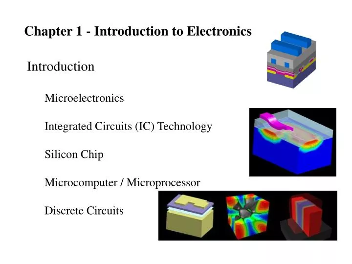
Chapter 1 - Introduction to Electronics. Introduction Microelectronics Integrated Circuits (IC) Technology Silicon Chip Microcomputer / Microprocessor Discrete Circuits. Signals Signal Processing Transducers. http://www.eas.asu.edu/~midle/jdsp/jdsp.html. Signals Voltage Sources

E N D
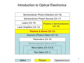
Chapter 1 - Introduction to Electronics • Introduction • Microelectronics • Integrated Circuits (IC) Technology • Silicon Chip • Microcomputer / Microprocessor • Discrete Circuits
Signals • Signal Processing • Transducers http://www.eas.asu.edu/~midle/jdsp/jdsp.html
Signals • Voltage Sources • Current Sources • Thevenin & Norton • http://www.clarkson.edu/%7Esvoboda/eta/ClickDevice/refdir.html • http://www.clarkson.edu/%7Esvoboda/eta/Circuit_Design_Lab/circuit_design_lab.html • http://www.clarkson.edu/%7Esvoboda/eta/CircuitElements/vcvs.html
Signals • Voltage Sources • Current Sources
Signals • Voltage Sources • Current Sources http://www.clarkson.edu/~svoboda/eta/ClickDevice/super.html http://javalab.uoregon.edu/dcaley/circuit/Circuit_plugin.html
Frequency Spectrum of Signals • Fourier Series • Fourier Transform • Fundamental and Harmonics • http://www.educatorscorner.com/experiments/spectral/SpecAn3.shtml frequency time
Frequency Spectrum of Signals • Fourier Series http://www.jhu.edu/%7Esignals/fourier2/index.html
Frequency Spectrum of Signals • Fourier Series
Frequency Spectrum of Signals • Fourier Series
Frequency Spectrum of Signals • Fourier Series
Frequency Spectrum of Signals • Fourier Series
Frequency Spectrum of Signals • Fourier Series
Frequency Spectrum of Signals http://www.jhu.edu/%7Esignals/fourier2/index.html http://www.jhu.edu/%7Esignals/listen/music1.html http://www.jhu.edu/%7Esignals/phasorlecture2/indexphasorlect2.htm
Analog and Digital Signals • Sampling Rate http://www.jhu.edu/%7Esignals/sampling/index.html • Binary number system • http://scholar.hw.ac.uk/site/computing/activity11.asp • Analog-to-Digital Converter • http://www.astro-med.com/knowledge/adc.html • http://www.maxim-ic.com/design_guides/English/AD_CONVERTERS_21.pdf • Digital-to-Analog Converter • http://www.maxim-ic.com/ADCDACRef.cfm
Amplifiers Vin Vout Voltage gain (Av) = Vout/Vin Linear - output is proportional to input Current amplifiers current gain (Ai) = Iout/Iin Power amplifiers power gain (Ap) = Pout/Pin
Amplifiers • Signal Amplification • Distortion • Non-Linear Distortion • Symbols • Gains – Voltage, Power, Current • Decibels • Amplifier Power Supplies • Efficiency
Amplifiers Gain in terms of decibels Typical values of voltage gain, 10, 100, 1000 depending on size of input signal Decibels often used when dealing with large ranges or multiple stages Av in decibels (dB) = 20log|Av| Ai in decibels (dB) = 20log|Ai| Ap in decibels (dB) = 10log|Ap| Av = 10 000 20log|10 000| = 80dB Av = 1000 20log|1000| = 60dB Av = 100 20log|100| = 40dB Av = 10 20log|10| = 20dB Av = -10 20log|-10| = 20dB Av = 0.1 20log|0.1| = -20dB Av negative - indicates a phase change (no change in dB) dB negative - indicates signal is attenuated
Amplifiers • Example 1.1
Amplifiers • Saturation An amplifier transfer characteristic that is linear except for output saturation. An amplifier transfer characteristic that is linear except for output saturation.
Amplifiers • Non-Linear Transfer Characteristics and Biasing An amplifier transfer characteristic that shows considerable nonlinearity. (b) To obtain linear operation the amplifier is biased as shown, and the signal amplitude is kept small.
Amplifiers Circuit model of a voltage amplifier + Vin - + Vout - • EPOLY is a dependent source is SPICE; a voltage controlled voltage source (VCVS) • EPOLY has a gain of Avo • The input to EPOLY is the voltage across Ri I = 0 Vout = Avo Vin Ri = input resistance Ro = output resistance
+ Vin - + Vout - Amplifiers Voltage amplifier with input source and load • What should we design Ro to be? • Av = Vout/Vin = Avo RL/(RL + Ro) • Let Ro < < RL to make Av maximum • Ideally Ro = 0 • Avo - gain of VCVS only, o indicates output is open • Av - gain of entire circuit • Av changes with circuit, Avo does not!
+ Vin - + Vout - Amplifiers Input resistance of amplifier circuit • What should we design Rin to be? • Vin = Vs Ri/(Ri + Rs) • Let Rin >> Rs to make Vin = Vs • Ideally Rin = infinity If Rin = infinity, then all of Vs makes it to the the amplifier; otherwise part of the signal is lost
Amplifiers Basic characteristics of ideal amplifier For maximum voltage transfer Rout = 0 Rin = infinity
Amplifiers • Example 1.2
Amplifiers • Example 1.2
Amplifiers • Example 1.2
Circuit Models For Amplifiers • Voltage Amplifiers • Common Models • Show example on board
Circuit Models For Amplifiers • Example 1.3 • Class assignment
Circuit Models For Amplifiers • Other Amplifiers • Current • Transconductance • Transresistance
Circuit Models For Amplifiers • Example 1.4 Large-signal equivalent-circuit models of the npn BJT operating in the active mode.
Frequency Response of Amplifiers • Bandwidth
Frequency Response of Amplifiers • Bandwidth • RC Circuits – Class Exercise • Single-Time Constant Networks • http://www.clarkson.edu/%7Esvoboda/eta/plots/FOC.html • http://www.clarkson.edu/%7Esvoboda/eta/acWorkout/Switched_RCandRL.html
Frequency Response of Amplifiers • Bandwidth (a) Magnitude and (b) phase response of STC networks of the low-pass type.
Frequency Response of Amplifiers • Bandwidth
Frequency Response of Amplifiers (a) Magnitude and (b) phase response of STC networks of the high-pass type.
Frequency Response of Amplifiers • Example 1.5 • Class assignment
Frequency Response of Amplifiers • Classification of Amplifiers • Based on Frequency Response
Frequency Response of Amplifiers • Exercise 1.6 • Class assignment
The Digital Logic Inverter • Function • Transfer Characteristics • Noise Margins
The Digital Logic Inverter • Function • Transfer Characteristics • Noise Margins
The Digital Logic Inverter • Inverter Implementation