Download
1 / 17
170 likes | 174 Views
Features of CNC Machining Centers. Lab 4: Identification. CNC Machine Components. Cutting Tool / Collet Caddy Very common to have 100 or more diverse cutting tools loaded into a collet caddy They are numbered for ease of identification

E N D
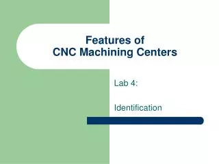
Features of CNC Machining Centers Lab 4: Identification
CNC Machine Components • Cutting Tool / Collet Caddy • Very common to have 100 or more diverse cutting tools loaded into a collet caddy • They are numbered for ease of identification • The operator must know the common tools by simple visual observation
CNC Bench Vise Notice the smooth machined surfaces; be careful not to damage surfaces
CAM & X-axis Table Alignment To machine a part with CNC, the end of the tool must be known relative to the bench vise, x-axis table, or some other fixed distance
Z-axis Arbor • Keep the lands clean and oiled • A slight tilt will cause noticeable cut deformations • Align the protrusions with slots in the cutting tool quick change adapter body
Air Nozzle Used for: • Keeping cutting area free of excessive cutting debris • Quick cleaning • When supplied with misting, provides cutting tool cooling
End Mill / Facing Cutter • Hogs off large amounts of material • Radius of cut very large • Provides a known surface from which to measure from • Requires workpiece to be robustly supported due to high torque created
Quick Change End Mill Adapter • Helps provide quick changing of cutting tools without having to use complex setup procedures
Power Panel • Lockable On-Off Switch • Circuit Breakers • Power Cord
Control Panel • 4.FEED SPEED CONTROL • Provides stepless control of tool feed speed in the X, Y and Z axes from 0 to 100% in 10% increments. • 5.JOG TABLE AXIS CONTROLS • These four buttons control manual movement of the table in the X and Y axes. • Move the table in the X axis while held pressed. • Move the table in the Y-axis while held pressed. • 6.JOG HEAD AXIS CONTROLS • Move the head in the Z axis while held pressed. • Pressing this button together with any of the other six axis control buttons provides rapid movement of the axes in the indicated direction.
Control Panel • 7.MANUALWhen lit, machine is operated from control panel (Manual mode). Pressing MAN puts light out and machine is controlled by computer (Automatic mode). Press MAN again to revert to manual mode operation. • 8.AIR MIST CONTROLSwitches on or off the optional air mist coolant when fitted. • 9.DATUM M/C - PROGRAM ABORT After initially powering up the machine and pressing the Power Reset button (23), with the machine in Manual mode (Manual mode button lit) press to datum the machine axes. • With the machine in Manual mode, the machine can be re-datumed at any point. This should always be done if a physical stall of the axes has occurred. • During an Automatic Cycle with a Feed Hold (1) active, pressing will Abort the current job.
Control Panel 10.TOOL CHANGEWith auto tool changer fitted, press to change to next tool automatically. 11.TOOL RELEASEReleases the tool holder from the spindle if fitted with the auto tool changer. Guard door must be open and tool holder held. 12.WORK HOLDING UN-CLAMPControls un-clamping of workpiece in pneumatic work holder vice, when fitted. 13. WORK HOLDING CLAMPControls clamping of workpiece in pneumatic work holder vice, when fitted. 14. DOOR OPENControls opening of the automatic doors when fitted.
Control Panel 15.DOOR CLOSEControls closing of the automatic doors when fitted. 16.SPINDLE CONTROLSThese control the speed and direction of rotation of the spindle. Spindle Forward - Pressing this button starts the spindle rotating forward. Holding it down increases forward speed. Pressing and holding the 'Spindle Reverse' button reduces speed in the forward direction. Spindle Reverse - Pressing this button starts the spindle rotating in reverse direction. Holding it down increases spindle speed in reverse direction. Pressing and holding the 'Spindle Forward' button reduces speed in the reverse direction. Spindle Stop - Pressing this button stops spindle rotation.
Control Panel 17.EMERGENCY STOPPressing this pushbutton stops all machine movement and switches off the electronics, and the button locks in the depressed position. If the machine is in production, an appropriate message is displayed on the PC screen. The button must be turned to release it and the Hard Reset button (23) pressed to enable the machine to be started. The machine must be datumed using the Datum M/C key (9). If the machine was performing a production cycle, the cycle must be repeated from the beginning.