Download
1 / 35
350 likes | 706 Views
Pulse-Width Modulation (PWM) Techniques. Lecture 2 5. Instructor: Prof. Ali Keyhani Contact Person: E-mail: keyhani.1@osu.edu Tel.: 614-292-4430. Department of Electrical and Computer Engineering The Ohio State University. 1. ORGANIZATION. I. Voltage Source Inverter (VSI)

E N D
Pulse-Width Modulation (PWM) Techniques Lecture 25 Instructor: Prof. Ali Keyhani Contact Person: E-mail: keyhani.1@osu.edu Tel.: 614-292-4430 Department of Electrical and Computer Engineering The Ohio State University 1
ORGANIZATION I. Voltage Source Inverter (VSI) A. Six-Step VSI B. Pulse-Width Modulated VSI II. PWM Methods A. Sine PWM B. Hysteresis (Bang-bang) C. Space Vector PWM III. References 2
I. Voltage Source Inverter (VSI) A. Six-Step VSI (1) • Six-Step three-phase Voltage Source Inverter Fig. 1 Three-phase voltage source inverter. 3
I. Voltage Source Inverter (VSI) A. Six-Step VSI (2) • Gating signals, switching sequence and line to negative voltages Fig. 2 Waveforms of gating signals, switching sequence, line to negative voltages for six-step voltage source inverter. 4
I. Voltage Source Inverter (VSI) A. Six-Step VSI (3) • Switching Sequence: 561 (V1) 612 (V2) 123 (V3) 234 (V4) 345 (V5) 456 (V6) 561 (V1) where, 561 means that S5, S6 and S1 are switched on Fig. 3 Six inverter voltage vectors for six-step voltage source inverter. 5
I. Voltage Source Inverter (VSI) A. Six-Step VSI (4) • Line to line voltages (Vab, Vbc, Vca) and line to neutral voltages (Van, Vbn, Vcn) • Line to line voltages • Vab = VaN - VbN • Vbc = VbN - VcN • Vca = VcN - VaN • Phase voltages • Van = 2/3VaN - 1/3VbN - 1/3VcN • Vbn = -1/3VaN + 2/3VbN - 1/3VcN • Vcn = -1/3VaN - 1/3VbN + 2/3VcN Fig. 4 Waveforms of line to neutral (phase) voltages and line to line voltages for six-step voltage source inverter. 6
I. Voltage Source Inverter (VSI) A. Six-Step VSI (5) • Amplitude of line to line voltages (Vab, Vbc, Vca) • Fundamental Frequency Component (Vab)1 • Harmonic Frequency Components (Vab)h : amplitudes of harmonics decrease inversely proportional to their harmonic order 7
I. Voltage Source Inverter (VSI) A. Six-Step VSI (6) • Characteristics of Six-step VSI • It is called “six-step inverter” because of the presence of six “steps” in the line to neutral (phase) voltage waveform • Harmonics of order three and multiples of three are absent from both the line to line and the line to neutral voltages and consequently absent from the currents • Output amplitude in a three-phase inverter can be controlled by only change of DC-link voltage (Vdc) 8
I. Voltage Source Inverter (VSI) B. Pulse-Width Modulated VSI (1) • Objective of PWM • Control of inverter output voltage • Reduction of harmonics • Disadvantages of PWM • Increase of switching losses due to high PWM frequency • Reduction of available voltage • EMI problems due to high-order harmonics 9
I. Voltage Source Inverter (VSI) B. Pulse-Width Modulated VSI (2) • Pulse-Width Modulation (PWM) Fig. 5 Pulse-width modulation. 10
I. Voltage Source Inverter (VSI) B. Pulse-Width Modulated VSI (3) • Inverter output voltage • When vcontrol > vtri, VA0 = Vdc/2 • When vcontrol < vtri, VA0 = -Vdc/2 • Control of inverter output voltage • PWM frequency is the same as the frequency of vtri • Amplitude is controlled by the peak value of vcontrol • Fundamental frequency is controlled by the frequency of vcontrol • Modulation Index (m) 11
II. PWM METHODS A. Sine PWM (1) • Three-phase inverter Fig. 6 Three-phase Sine PWM inverter. 12
vcontrol_C vcontrol_B vtri vcontrol_A II. PWM METHODS A. Sine PWM (2) • Three-phase sine PWM waveforms • Frequency of vtri and vcontrol • Frequency of vtri = fs • Frequency of vcontrol = f1 where, fs = PWM frequency f1 = Fundamental frequency • Inverter output voltage • When vcontrol > vtri, VA0 = Vdc/2 • When vcontrol < vtri, VA0 = -Vdc/2 where, VAB = VA0 – VB0 VBC = VB0 – VC0 VCA = VC0 – VA0 Fig. 7 Waveforms of three-phase sine PWM inverter. 13
II. PWM METHODS A. Sine PWM (3) • Amplitude modulation ratio (ma) • Frequency modulation ratio (mf) • mf should be an odd integer • if mf is not an integer, there may exist sunhamonics at output voltage • if mf is not odd, DC component may exist and even harmonics are present at output voltage • mf should be a multiple of 3 for three-phase PWM inverter • An odd multiple of 3 and even harmonics are suppressed 14
II. PWM METHODS B. Hysteresis (Bang-bang) PWM (1) • Three-phase inverter for hysteresis Current Control Fig. 8 Three-phase inverter for hysteresis current control. 15
II. PWM METHODS B. Hysteresis (Bang-bang) PWM (2) • Hysteresis Current Controller Fig. 9 Hysteresis current controller at Phase “a”. 16
II. PWM METHODS B. Hysteresis (Bang-bang) PWM (3) • Characteristics of hysteresis Current Control • Advantages • Excellent dynamic response • Low cost and easy implementation • Drawbacks • Large current ripple in steady-state • Variation of switching frequency • No intercommunication between each hysterisis controller of three phases and hence no strategy to generate zero-voltage vectors. As a result, the switching frequency increases at lower modulation index and the signal will leave the hysteresis band whenever the zero vector is turned on. • The modulation process generates subharmonic components 17
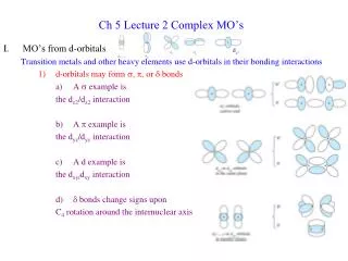
II. PWM METHODS C. Space Vector PWM (1) • Output voltages of three-phase inverter (1) where,upper transistors: S1, S3, S5 lower transistors: S4, S6, S2 switching variable vector: a, b, c Fig. 10 Three-phase power inverter. 18
II. PWM METHODS C. Space Vector PWM (2) • Output voltages of three-phase inverter (2) S1 through S6 are the six power transistors that shape the ouput voltage When an upper switch is turned on (i.e., a, b or c is “1”), the corresponding lower switch is turned off (i.e., a', b' or c' is “0”) • Eight possible combinations of on and off patterns for the three upper transistors (S1, S3, S5) Line to line voltage vector [Vab Vbc Vca]t Line to neutral (phase) voltage vector [Van Vbn Vcn]t 19
II. PWM METHODS C. Space Vector PWM (3) • Output voltages of three-phase inverter (3) • The eight inverter voltage vectors (V0 to V7) 20
II. PWM METHODS C. Space Vector PWM (4) • Output voltages of three-phase inverter (4) • The eight combinations, phase voltages and output line to line voltages 21
II. PWM METHODS C. Space Vector PWM (5) • Principle of Space Vector PWM • Treats the sinusoidal voltage as a constant amplitude vector rotating at constant frequency • This PWM technique approximates the reference voltage Vref by a combination of the eight switching patterns (V0 to V7) • CoordinateTransformation (abc reference frame to the stationary d-q frame) : A three-phase voltage vector is transformed into a vector in the stationary d-q coordinate frame which represents the spatial vector sum of the three-phase voltage • The vectors (V1 to V6) divide the plane into six sectors (each sector: 60 degrees) • Vref is generated by two adjacent non-zero vectors and two zero vectors 22
II. PWM METHODS C. Space Vector PWM (6) • Basic switching vectors and Sectors • 6 active vectors (V1,V2, V3, V4, V5, V6) • Axes of a hexagonal • DC link voltage is supplied to the load • Each sector (1 to 6): 60 degrees • 2 zero vectors (V0, V7) • At origin • No voltage is supplied to the load Fig. 11 Basic switching vectors and sectors. 23
II. PWM METHODS C. Space Vector PWM (7) • Comparison of Sine PWM and Space Vector PWM (1) Fig. 12 Locus comparison of maximum linear control voltage in Sine PWM and SV PWM. 24
II. PWM METHODS C. Space Vector PWM (8) • Comparison of Sine PWM and Space Vector PWM (2) • Space Vector PWM generates less harmonic distortion in the output voltage or currents in comparison with sine PWM • Space Vector PWM provides more efficient use of supply voltage in comparison with sine PWM • Sine PWM : Locus of the reference vector is the inside of a circle with radius of 1/2 Vdc • Space Vector PWM : Locus of the reference vector is the inside of a circle with radius of 1/3 Vdc Voltage Utilization: Space Vector PWM = 2/3 times of Sine PWM 25
II. PWM METHODS C. Space Vector PWM (9) • Realization of Space Vector PWM • Step 1. Determine Vd, Vq, Vref, and angle () • Step 2. Determine time duration T1, T2, T0 • Step 3. Determine the switching time of each transistor (S1 to S6) 26
II. PWM METHODS C. Space Vector PWM (10) • Step 1. Determine Vd, Vq, Vref, and angle () • Coordinate transformation : abc to dq Fig. 13 Voltage Space Vector and its components in (d, q). 27
II. PWM METHODS C. Space Vector PWM (11) • Step 2. Determine time duration T1, T2, T0 (1) Fig. 14 Reference vector as a combination of adjacent vectors at sector 1. 28
II. PWM METHODS C. Space Vector PWM (12) • Step 2. Determine time duration T1, T2, T0 (2) • Switching time duration at Sector 1 29
II. PWM METHODS C. Space Vector PWM (13) • Step 2. Determine time duration T1, T2, T0 (3) • Switching time duration at any Sector 30
II. PWM METHODS C. Space Vector PWM (14) • Step 3. Determine the switching time of each transistor (S1 to S6) (1) (a) Sector 1. (b) Sector 2. Fig. 15 Space Vector PWM switching patterns at each sector. 31
II. PWM METHODS C. Space Vector PWM (15) • Step 3. Determine the switching time of each transistor (S1 to S6) (2) (c) Sector 3. (d) Sector 4. Fig. 15 Space Vector PWM switching patterns at each sector. 32
II. PWM METHODS C. Space Vector PWM (16) • Step 3. Determine the switching time of each transistor (S1 to S6) (3) (e) Sector 5. (f) Sector 6. Fig. 15 Space Vector PWM switching patterns at each sector. 33
II. PWM METHODS C. Space Vector PWM (17) • Step 3. Determine the switching time of each transistor (S1 to S6) (4) Table 1. Switching Time Table at Each Sector 34
III. REFERENCES [1] N. Mohan, W. P. Robbin, and T. Undeland, Power Electronics: Converters, Applications, and Design, 2nd ed. New York: Wiley, 1995. [2] B. K. Bose, Power Electronics and Variable Frequency Drives:Technology and Applications. IEEE Press, 1997. [3] H.W. van der Broeck, H.-C. Skudelny, and G.V. Stanke, “Analysis and realization of a pulsewidth modulator based on voltage space vectors,” IEEE Transactions on Industry Applications, vol.24, pp. 142-150, 1988. 35