Download
1 / 20
200 likes | 307 Views
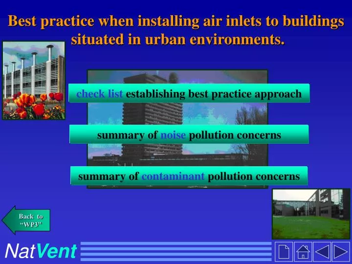
Best practice when installing air inlets to buildings situated in urban environments. check list establishing best practice approach. summary of noise pollution concerns. summary of contaminant pollution concerns. Back to “WP3”. Nat Vent. Introduction.

E N D
Best practice when installing air inlets to buildings situated in urban environments. check listestablishing best practice approach summary of noise pollution concerns summary of contaminant pollution concerns Back to “WP3” NatVent
Introduction A common barrier when adopting natural ventilation in buildings located in urban environments is the potential exposure to external pollutants. Whilst mechanical ventilation systems can draw air through cleaning filters the driving pressures associated with naturally ventilated buildings are too low. A strategy suitable for naturally ventilated buildings includes, identifying sources of pollution surrounding buildings and positioning air inlet devices in a sensible way. The interactive design tool identifies all urban sources of pollution and indicates how different ventilation approaches will determine the type of pollution control features required within air inlets. Since size of air inlets in relation to ventilation performance is also an important issue, design tools are attached that calculate appropriate opening areas. Back to “WP3”
How to use this tool Checklist: This is a comprehensive list of tables, set out in a concise order, that allows the user to establish the types of pollutants that are a potential problem to their building. The user should approach the tables from the start, whereupon guidance as to the next issue for consideration is provided through interactive links. At the end of this process it will become clear which type of pollution control air inlet device is required. Finally the size of openings required in buildings can be established using the natural ventilation design tools. Flow charts: These provide an overview of all pollution sources in urban environments, as well as avoidance strategies. At all stages interactive links enable the user to access the tables described above where more detail is provided. Back to “WP3”
Summary of noise pollution concerns Noise pollution sources Railways (table A) Exhaust vents (table C,1) Airports/Aircraft (table A) Car parks (table A) Busy roads (table A) far near far near far near near far Non rush hour period (table A) Rush hour / constant use (table A) Attenuation of noise is not required (table E, 1) Attenuate noise levels (table E, 1&2) Attenuation of noise is not required (table E, 1) Location of inlet (table B, 1) Loaction of inlet (table B, 1) Attenuation of noise is not required (table E, 1) street level roof level Exposed façade (tables C& D) Sheltered façade (table A) Moderate attenuation required (table E, 1) Attenuate noise levels (table E, 1&2) Attenuate noise levels (table E, 1&2) Attenuation of noise is not required (table E, 1) Noise pollution sources are ‘near’ if levels exceed 55 dBA by the facade
Summary of contaminant pollution concerns Contaminant pollution sources Local industry (table D, 3) Exhaust vents (table C,1) Exhaust vents from other buildings (table D, 1) Car parks (table A) Busy roads (table A) far near far near unshielded shielded unshielded Attenuation of contaminants is not required (table E) Attenuation of contaminants is not required (table E) Attenuation of contaminants is not required (table E) Rush hour / constant use (table A) Non rush hour period (table A) Downwind source (table C & D) Upwind source (table C & D) Air inlet location (table B, 1) Dilution factor (table C, 2) ineffective effective high low Attenuation of contaminants is not required (table E) Attenuate contaminants levels (table E) Attenuation of contaminants is not required (table E) Attenuate contaminants levels (table E)
Check list for the location of air inlets to buildings - overview (1…) OVERVIEW Table A:Location of facade relative to transport generated pollutants. Table B(1): Height of air intakes. Table B(2): Alternative pollution sources. Table C(1): Building exhaust vent problems. Table C(2): Dilution of exhaust gases. Table D(1): Proximity to other buildings. Table D(2): Noise associated with environment. Table D(3): Proximity to industrial emissions. Table E(1): Air inlet design features. Table E(2): Office use in relation to noise attenuation requirements.
Check list for the location of air inlets to buildings - overview (2…) Table A Location of facade relative to transport related Attenuation requirements Move to table: pollutants particles noise Close to busy roads or bus stops, traffic lights yes yes B (1) and junctions Far from busy roads . no no C & D Sheltered facade (Enclosure & courtyards). no no C & D Near main railway lines. no yes C & D Near airports and flight paths no yes C & D Near large scale car parks: - rush hour periods. yes yes B (2) - non rush hour periods. no no C & D
Check list for the location of air inlets to buildings - Table B (3…) Table B (1) Attenuation requirements Move to table: Height of air intakes : particles noise Above 10 m. no yes C & D Below 10 m. yes yes E (1)-5 Table B (2) Alternative pollution sources: Move to table: None present. E (1)-2 Alternative sources present. C & D
Check list for the location of air inlets to buildings - Table C1 (4…) Building exhaust vent problems Pollution risk Move to table: contaminants noise Location on windward facade: yes rd - distance between vent & inlet < 1/ 3 yes C (2) building height. no rds - distance between vent & inlet > 2 /3 no D (1) Table C (1) building height. yes - distance between vent & inlet > 1/3 rd yes C (2) rds and < 2 / 3 building height. Location on cross wind facade: - vent near roof & inlet near ground. no no D (1) - vent near ground & inlet near roof. no no D (1) - vent & inlet near roof. yes yes C (2) - vent & inlet near ground. yes yes C (2) Location on leeward facade: D (1) - vent near ground & inlet, mid - high no no D (1) - vent near roof & inlet, mid - high no no - vent, mid facade & inlet, low - high no no D (1) - vent & inlet near roof. yes yes C (2) - vent & inlet near ground. yes yes C (2) - vent & inlet at mid facade level. yes yes C (2) Location on roof: - vent & inlet are relatively ‘close’ yes yes C (2)
Check list for the location of air inlets to buildings - Table C2 (5…) Table C (2) Attenuation requirements Move to table: Dilution of exhaust gases contaminants noise Minimum dilution is effective no no D (1) Minimum dilution is ineffective yes yes E (1)-5
Check list for the location of air inlets to buildings - Table D1 (8…) Re-ingestion Move to table: Proximity to other buildings : problems Tall neighboring building, on windward side: yes - air intake for host building is on windward side. D (2) Table D (1) - air intake for host building is on leeward side. no D (3) no - air intake for host building is on cross wind sides. D (3) Short neighboring building, on windward side: no - air intake for host building is on windward side, at high level. D (3) - air intake for host building is on windward side, at low level. yes D (2) no - air intake for host building is on leeward side. D (3) - air intake for host building is on cross wind sides. no D (3) Tall neighboring building, on leeward side: - air intake for host building is on windward side. no D (3) yes - air intake for host building is on leeward side. D (2) - air intake for host building is on cross wind sides. no D (3) Short neighboring building, on leeward side: - air intake for host building is on windward side. no D (3) - air intake for host building is on leeward side, at high level. no D (3) - air intake for host building is on leeward side, at low level. yes D (2) - air intake for host building is on cross wind sides. no D (3)
Check list for the location of air inlets to buildings - Table D2 (9…) Table D (2) Attenuation requirements Noise associated with environment Move to table: noise contaminants Minimum dilution of contaminants is effective. - Noisy location. no yes E (1) -3 -Quiet location no no E (1) -1 Minimum dilution of pollutants is ineffective - Noisy location. yes yes E (1) -5 -Quiet location yes no E (1) -4
Check list for the location of air inlets to buildings - Table D3 (10…) Table D (3) Re-ingestion Move to table Proximity to industrial emissions : problems yes Quiet location with local industrial emissions on windward side. E (1) -5 no Noisy location with local industrial emissions on windward side. E (1) -3 yes Noisy location with local industrial emissions on leeward side. E (1) -4 no Quiet location with local industrial emissions on leeward side. E (1) -1 no Noisy location with no local industrial emissions. E (1) -1 Quiet location with no local industrial emissions. no E (1) -1
Check list for the location of air inlets to buildings - Table E1 (11…) Table E (1) E(2) skip to Tools for sizing air inlets E(2) E(2)
Check list for the location of air inlets to buildings - Table E1 (12|) Table E (2) Nature of office on noise attenuation requirements : description of room noise attenuation features desired - excellent noise attenuation required for rooms. - locate rooms on sheltered facades if possible. skip to Tools for sizing air inlets Noise sensitive offices. - locate rooms near ground level where aircraft noise is a problem. - additional air inlet noise attenuation required Open plan offices. to account for reduction in partition area. - comparatively less noise attenuation required Cellular offices. for air inlet due to greater room absorption.
Models for calculating vent opening size (click on icon to open the model) Sizing model Models for assessing indoor air quality & thermal comfort The NavIAQ program (for more information: go back to Main The Final Products) The NatVent program (for more information: go back to Main The Final Products)
CONTENTS More information... Noise pollution Contaminant pollution List of tables You can find more information on: Air Inlets in Urban Environment (calculations, acoustic-filter vent, etc) in the documents: • \Reports\ Technological solutions\ 3.1_air supply 1.pdf • \Reports\ Technological solutions \ 3.1_air supply 2.pdf Design tools You can read and print pdf-files with the Acrobat® Reader ®3.0. Program. This program is free. Download it from the Acrobat web site: www.adobe.com OR run the installation file ar32e301(1).exe in the directory \Installation Back to “WP3” Acoustic-filter developed in the framework of Work Package 3.1. NatVent