Download
1 / 18
180 likes | 201 Views
Ekeeda Provides Online Electrical and Electronics Engineering Degree Subjects Courses, Video Lectures for All Engineering Universities. Video Tutorials Covers Subjects of Mechanical Engineering Degree.

E N D
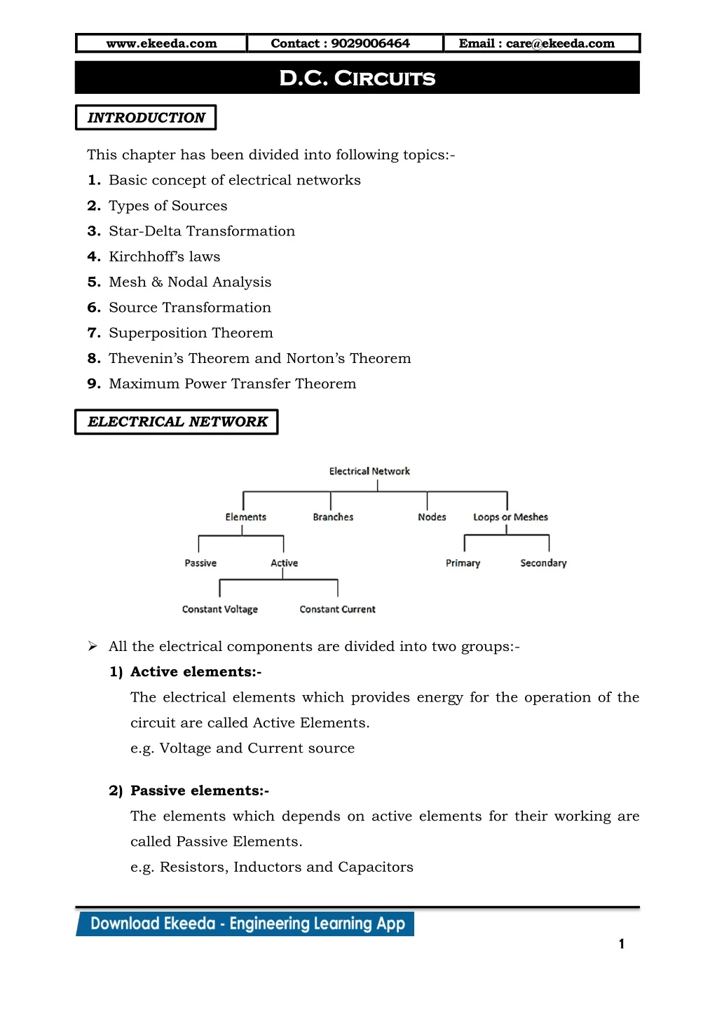
www.ekeeda.com Contact : 9029006464 D.C. Circuits D.C. Circuits Email : care@ekeeda.com P INTRODUCTION This chapter has been divided into following topics:- 1.Basic concept of electrical networks 2.Types of Sources 3.Star-Delta Transformation 4.Kirchhoff’s laws 5.Mesh & Nodal Analysis 6.Source Transformation 7.Superposition Theorem 8.Thevenin’s Theorem and Norton’s Theorem 9.Maximum Power Transfer Theorem ELECTRICAL NETWORK All the electrical components are divided into two groups:- 1)Active elements:- The electrical elements which provides energy for the operation of the circuit are called Active Elements. e.g. Voltage and Current source 2)Passive elements:- The elements which depends on active elements for their working are called Passive Elements. e.g. Resistors, Inductors and Capacitors 1
www.ekeeda.com Contact : 9029006464 Email : care@ekeeda.com Types of Electrical Network 1)Linear Network:- A network whose parameters (resistor, inductors and capacitor) are always constant irrespective of the changes in time, voltage, temperature etc. is known as Linear Network. 2)Non-Linear Network:- A network whose parameters change their values with change in time, temperature, voltage etc. is known as Non-Linear Network. 3)Unilateral Network:- A network whose operation is dependent on the direction of the current through various elements is called Unilateral Network. e.g. Circuits consisting of diodes, SCR etc. 4)Bilateral Network:- A network whose operation is independent of the direction of the current through various elements is called Bilateral Network. e.g. Resistive Networks Types of Sources The sources are basically classified as: i) Ideal Source ii) Practical Source Ideal Voltage Source:- a)An ideal voltage source is defined as a source which maintains constant voltage across its terminals regardless of current drawn from it. b)It has zero internal resistance. Ideal voltage source and its characteristics is sown in figure. 2
www.ekeeda.com Contact : 9029006464 Email : care@ekeeda.com Practical Voltage Source:- a)A practical voltage source is defined as a source which consists of some internal resistance Rse in series. b)As the current drawn from source increases the voltage drop ILRse increases across internal resistance. c)This reduces the terminal voltage across the load. The characteristics of practical voltage source is shown in figure. Ideal Current Source:- a)The ideal current source is defined as a source which gives constant specified current at its terminals, irrespective of the voltage appearing across its terminals. b)The characteristics of ideal current source is shown in figure: Practical Current Source: a)A practical current source is defined as a source which consists of internal resistance Rsh in parallel. b)As the load resistance increases the current supplied by the source decreases. c)This fall in current is due to the internal resistance of the source. The characteristics of practical current source is shown in figure. 3
www.ekeeda.com Contact : 9029006464 Email : care@ekeeda.com SERIES CIRCUIT 1)Consider Resistors R1, R2, …., Rn connected to from a series circuit. 2)Following points can be concluded for series circuit:- a)The current flowing through each resistor is the same i.e. I. b)The potential difference across resistors R1, R2, …, Rn are V1 = IR1, V2 = I R2, …, Vn = IRn respectively. c)Also applied voltage gets distributed across resistors i.e. VT = V1 + V2+….+ Vn. d)The net or equivalent resistance of the series circuit is given by, Req = R1 + R2+ … + Rn. e)There are no junctions and the same current I flow through the single path. Voltage Division Rule Referring to the above figure we have, V I = R T eq V I = R +R +....+R T 1 2 n Therefore, voltage across R1 is, V V I R R T 1 1 1 ... R R R 1 2 n Similarly, V V I R R T 2 2 2 ... R R R 1 2 n V V I R R T n n n ... R R R 1 2 n 4
www.ekeeda.com Contact : 9029006464 Email : care@ekeeda.com PARALLEL CIRCUIT 1)Consider Resistors R1, R2, … , Rn connected to form a parallel circuit. 2)Following points can be concluded for parallel circuit: a)The Voltage across each resistor is the same i.e. V. b)The current through resistors R1, R2,…., Rn are V V I = ,I = ,...,I = R R c)Also current gets divided through resistors i.e. IT = I1 + I2+ … + In. d)The net or equivalent resistance of the parallel circuit is given by, 1 1 1 1 = + + .... + R R R R e)There are junctions and the total current ‘I’ gets divided at these junctions. Current Division Rule Referring to the adjacent figure we have, R R R R R V = R I = R I = R I V I =R V R respectively. 1 2 n 1 2 n eu 1 2 n 1 2 eq 1 2 Also, T 1 1 2 2 1 1 R R eq I = I 1 1 R R I = I Similarly, I 2 1 1 2 R +R R +R 1 2 1 2 5
www.ekeeda.com Contact : 9029006464 Email : care@ekeeda.com DELTA TO STAR AND STAR TO DELTA TRANSFORMATION 1)There are some networks in which the resistances are neither in series nor in parallel. A familiar case is a three terminal network e.g. delta network or star network. 2)In such situations, it is not possible to simplify the network by series and parallel circuit rules. However, converting delta network into star and vice- versa often simplifies the network and makes it possible to apply series parallel circuit techniques. Delta to Star transformation 1)Consider three resistors RA, RB, RC connected in delta to three terminals 1, 2 and 3 as shown in the figure (a). It is desired to replace these three delta connected resistors by three resistors R1, R2, R3 connected in star so that the two networks are electrically equivalent. 2)The two arrangements will be electrically equivalent if resistance between any two terminals of one network is equal to the resistance between the corresponding terminals of the other network. (a) (b) 6
www.ekeeda.com Contact : 9029006464 Email : care@ekeeda.com 3)Referring to fig. (a) Resistance between 1 and 2 = Rc|| (RA + RB) R R +R +R R +R c A B = ….(1) A B C 4)Also from figure (b), Resistance between 1 and 2 = R1 + R2 …. (2) 5)Since, two arrangements are electrically equivalent, R R R R c A B R ….. (3) R R 1 2 R A B C Similarly, R R +R A B C ….. (4) R +R =R +R +R 2 3 A B C R (R +R ) ….. (5) R +R =R +R +R B C A 3 1 A B C 6)Subtracting equation (4) from equation (3) and adding the result to equation (5) we get, R R ….. (6) R =R +R +R B C 1 A B C R R Similarly, …... (7) R =R +R +R C A 2 A B C R R And ….. (8) R =R +R +R A B 3 A B C 7
www.ekeeda.com Contact : 9029006464 Email : care@ekeeda.com Star to Delta transformation 1)Dividing equation (6) by equation (7), we get R R R R R R = R = 1 B 1 R A B 2 A 2 2)Dividing equation (6) by equation (8), we get R R R R R R = R = C 1 1 R A C 3 A 3 3)Substituting the value of RB and RC in equation (6) we have R R R R 1 R R R R A 1 R A 2 3 R R R R = 1 R + + 1 A 1 A A 2 3 2 1 R R R R R 2 3 = R A R R 1+ + 1 1 2 3 2 1 R = R A R R +R R +R R R R +R R +R R R 1 2 2 3 3 1 R = 1 2 2 3 3 1 A 1 R R R R = R + R + 2 3 A 2 3 1 R R R R R R Similarly, R = R + R + 3 1 B 3 1 2 and R = R + R + 1 2 C 1 2 3 Kirchhoff’s Laws Entire electric circuit analysis is based on Kirchhoff’s laws. But before discussing this it is essential to familiarise with some terms: a)Node:- Node is a junction where two or more circuit elements are connected together. b)Branch:- An element or number of elements connected between two nodes constitutes a branch. c)Loop: Loop is any closed part of the circuit. 8
www.ekeeda.com Contact : 9029006464 Email : care@ekeeda.com d)Mesh: Mesh is the most elementary form of the loop and cannot be further divided into other loops. Hence, all the meshes are loops but all the loops are not meshes. KIRCHHOFF’S CURRENT LAW (KCL) Statement: The algebraic sum all the currents meeting at a junction or node in an electric circuit is zero. i.e. I = 0 e.g. Consider five conductors carrying currents I1, I2, I3, I4 and I5 meeting at point O as shown below. Assuming the incoming currents to be positive and outgoing currents negative, we have I + (-I ) + I + I + (-I ) = 0 1 2 3 4 5 I + I + I = I + I 1 3 4 2 5 Thus, the above law can also be stated as the sum of currents flowing towards any junction in an electric circuit is equal to the sum of the current flowing away from the junction. 9
www.ekeeda.com Contact : 9029006464 Email : care@ekeeda.com KIRCHHOFF’S VOLTAGE LAW (KVL) Statement: The algebraic sum of all the voltages in any closed mesh or loop is zero. Sign Conventions: i.e. IR+ E = 0 a)Sign of a battery:- A rise in voltage is considered as positive, whereas fall in voltage is considered as negative. (a) Rise in Voltage (b) Fall in Voltage b)Sign of I R drop:- If we go through the resistance in the same direction as the current, there is fall in the potential so the sign of voltage drop is negative. If we go opposite to the direction of current flow, there is a rise in potential and hence, this voltage drop should be given negative sign. (a) Fall in Voltage (b) Rise in Voltage Mesh Analysis 1)In this method, KVL is applied to a network to write mesh equations in terms of mesh currents instead of branch currents. 2)Each mesh is assigned a separate mesh current. KVL is then applied to write equations in terms of unknown mesh currents. 3)The number of equations formed is equal to the number of unknown mesh currents. Once the mesh currents are known, the branch currents can be easily determined. 4)Steps to be followed in Mesh Analysis: a)Identify the mesh, assign a direction to it and assign an unknown current in each mesh. 10
www.ekeeda.com Contact : 9029006464 Email : care@ekeeda.com b)Assign the polarities for voltage across the branches. c)Apply KVL around each mesh. d)Solve the simultaneous equations for unknown mesh currents. Advantages: 1)Simpler method as compared to Kirchhoff’s Branch current method. 2)Currents through all the branches of a given network can be found. Disadvantages: 1)If the current through only a particular branch is required, then this method is lengthy. 2)Inconvenient for the circuits containing constant current source. Nodal Analysis 1)In this method, one of the node is taken as the reference node and the potential of all the remaining nodes in the circuit are measured w.r.t. this reference node. 2)For finding out these voltages, KCL is used as the various junctions. Thus for an electrical network having ‘n’ nodes the number of simultaneous equations to be solved is (n-1). 3)Steps to be followed in Nodal Analysis: a)Assuming that network has ‘n’ nodes, assign a reference node and the reference directions and assign node voltages. b)Apply KCL at each node except for references node. c)Solve the simultaneous equations for the unknown node voltages. d)Using these node voltages, find any branch currents required. 11
www.ekeeda.com Contact : 9029006464 Email : care@ekeeda.com Source Transformation and Source Shifting Rule 1: Voltage to Current Source Conversion 1)A voltage source with a series resistance can be converted into an equivalent current source with a parallel resistance. 2)Conversely, a current source with a parallel resistance can be converted into voltage source with a series resistance. Rule 2: Voltage Sources in Series Rule 3: Voltage Sources in Parallel Rule 4: Current Sources in Series 12
www.ekeeda.com Contact : 9029006464 Email : care@ekeeda.com Rule 6: Shifting of Voltage Source Rule 5: Current Sources in Parallel Rule 7: Shifting of Current Source 13
www.ekeeda.com Contact : 9029006464 Email : care@ekeeda.com Superposition Theorem Statement:- In a linear network containing more than one active source, the resultant current in any element is the algebraic sum of all the currents that would be produced by each source acting alone, all the other sources being replaced by their respective internal resistances. 1)The constant voltage sources are represented by their internal resistance if given. If it is not given replace it by short circuit. 2)The constant current sources are represented by infinite resistance i.e. open circuit. Advantages: 1)The current through a particular branch can be found very quickly. Disadvantages: 1)This method can be used only for those circuits containing more than one source. 2)If currents through all the branches are required then this method is lengthy. Thevenin’s Theorem Statement:- Any two terminal bilateral, linear network containing passive elements can be converted into a single equivalent voltage source known as ‘Thevenin’s voltage source’ in series with a single equivalent resistor known a ‘Thevenin’s resistance’. Steps to be followed in Thevenin’s Theorem: 1)Remove the load resistance RL. 2)Find open circuit voltage VTH across points A and B. 14
www.ekeeda.com Contact : 9029006464 Email : care@ekeeda.com 3)Find the resistance RTH as seen from point A and B with all the sources replaced by their internal resistances. 4)Replace the entire network by voltage source VTH in series with resistance RTH. 5)Find the current through RLusing ohm’s law. V I =R TH +R L TH L . Advantages: 1)It reduces a complex circuit to a simple circuit i.e. single voltage source and a single resistance. 2)It greatly simplifies the portion of the circuit of lesser interest and enables us to view the action of the output part directly. 3)The theorem is used to find the current in a particular branch of a network. Disadvantages: 1)If currents through all the branches are required then this method is lengthy. 15
www.ekeeda.com Contact : 9029006464 Email : care@ekeeda.com Norton’s Theorem Statement:- Any two terminal bilateral, linear network containing passive elements can be converted into a single equivalent current source known as ‘Norton’s current source’ in parallel with a single equivalent resistor known as ‘Norton’s resistance’. Steps to be followed in Norton’s Theorem: 1)Remove the load resistance RL. 2)Find short circuit current IN. 3)Find the resistance RN as seen from point A and B with all the sources replaced by their internal resistance. 4)Replace the entire network by current source IN in parallel with resistance RN. 5)Find the current through RL using current divider rule. R I = I N L SC R +R N L . 16
www.ekeeda.com Contact : 9029006464 Email : care@ekeeda.com Maximum Power Transfer Theorem Statement:- In any two terminal bilateral, linear network containing passive elements maximum power is delivered to a load from a source when the load resistance is made equal to the source resistance. i.e. PLoad is maximum only when RL = RS Proof:- 1)Consider a load resistance RL connected across the terminals A and B of a network which consists of a voltage source ES with internal resistance RS. E 2)The circuit current is I = R +R S L S Power consumed by the load is, 2 S E R 2 ……. (1) P = I R =R +R L L L 2 S L 3)For a given source or circuit ES and RS are constant. Therefore power delivered to the load depends on RL only. Thus, for PL to be maximum dP dR =0 L L 17
www.ekeeda.com Contact : 9029006464 Email : care@ekeeda.com 4)Therefore, differentiating equation (1) we get, 4 S 2 S R +R (1)-(R ) 2R +R R +R dP dR L L L S 2 S = E L L L 2 S 2 L R -R R +R dP dR 2 S =E L 4 S L L R -R R +R dP dR 2 S =E S L L 3 S L L dP dR But, =0 L L R R R R 2 S 0 E S L 3 S R R L R hence, the Proof. 0 R S L L S 5)Also maximum power transferred to the load is, 2 S 2 S E R R +R E R 2R Lmax P = = L S 2 S 2 S L 2 S E Lmax P =4R s 18