Download
1 / 8
80 likes | 83 Views
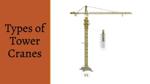
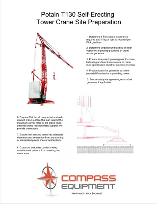
Self erecting tower cranes are particularly well suited for small building sites because they are quick, nimble, and simple to use is provided by compass equipment.<br>

E N D
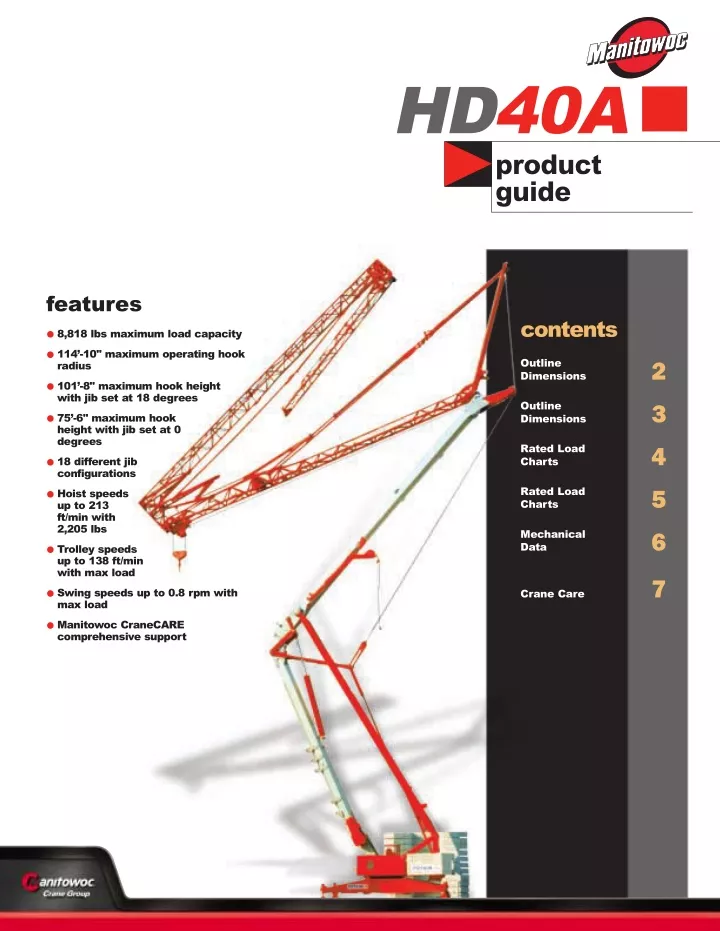
HD40A product guide features •8,818 lbs maximum load capacity •114’-10" maximum operating hook radius •101’-8" maximum hook height with jib set at 18 degrees •75’-6" maximum hook height with jib set at 0 degrees •18 different jib configurations •Hoist speeds up to 213 ft/min with 2,205 lbs •Trolley speeds up to 138 ft/min with max load •Swing speeds up to 0.8 rpm with max load •Manitowoc CraneCARE comprehensive support contents Outline Dimensions 2 Outline Dimensions 3 Rated Load Charts 4 Rated Load Charts 5 Mechanical Data 6 7 Crane Care
outline dimensions 2 HD40A
outline dimensions 118 112 106 99 3 92 86 79 73 66 59 53 46 40 33 26 20 13 7 0 13 7 0 7 13 20 26 33 40 46 53 59 66 73 79 86 92 99 106 112 118 (OL) 8'2" (MBL) DJ105 / S125 Dimensions During Transport Weights During Transport (without cab) (MOH) Overall Length, (OL) = 50'-0" Total Crane - With "A" & "B" Blocks 42,681 lbs Overhang, (OH) = 17'-5" Weight under Fifth Wheel 19,312 lbs Maximum Overall Height, (MOH) = 11'-8" Weight under Rear Axle 23,369 lbs Overall Width, (OW) = 8'-2" Weight of each "A" Block 4,740 lbs Fifth Wheel to C.L. Rotation, (FWR) = 8'-2" Weight of each "B" Block 3,417 lbs (AS) (OH) Axle Spacing, (AS) = 24'-5" Permissible Ballast During Transport 9,480 lbs DJ80 / S120 DJ126M / S125 Dimensions During Transport Weights During Transport (without cab) Dimensions During Transport Weights During Transport (without cab) Overall Length, (OL) = 50'-0" Total Crane - With "A" & "B" Blocks 41,579 lbs Overall Length, (OL) = 52'-2" Total Crane - With "A" & "B" Blocks 48,281 lbs Overhang, (OH) = 17'-5" Weight under Fifth Wheel 18,585 lbs Overhang, (OH) = 17'-5" Weight under Fifth Wheel 25,133 lbs Maximum Overall Height, (MOH) = 11'-2" Weight under Rear Axle 22,994 lbs Maximum Overall Height, (MOH) = 11'-10" Weight under Rear Axle 23,149 lbs Overall Width, (OW) = 8'-2" Weight of each "A" Block 4,740 lbs Overall Width, (OW) = 8'-2" Weight of each "A" Block 4,740 lbs Fifth Wheel to C.L. Rotation, (FWR) = 8'-2" Weight of each "B" Block 3,417 lbs Fifth Wheel to C.L. Rotation, (FWR) = 8'-2" Weight of each "B" Block 3,417 lbs Axle Spacing, (AS) = 24'-5" Permissible Ballast During Transport 9,480 lbs Axle Spacing, (AS) = 24'-5" Permissible Ballast During Transport 16,314 lbs DJ100 / S120 DJ126M / S215M Dimensions During Transport Weights During Transport (without cab) Dimensions During Transport Weights During Transport (without cab) Overall Length, (OL) = 50'-0" Total Crane - With "A" & "B" Blocks 42,042 lbs Overall Length, (OL) = 54'-8" Total Crane - With "A" & "B" Blocks 51,809 lbs Overhang, (OH) = 17'-5" Weight under Fifth Wheel 19,136 lbs Overhang, (OH) = 17'-10" Weight under Fifth Wheel 22,708 lbs Maximum Overall Height, (MOH) = 11'-8" Weight under Rear Axle 22,906 lbs Maximum Overall Height, (MOH) = 12'-11" Weight under Rear Axle 29,101 lbs Overall Width, (OW) = 8'-2" Weight of each "A" Block 4,740 lbs Overall Width, (OW) = 8'-2" Weight of each "A" Block 4,740 lbs Fifth Wheel to C.L. Rotation, (FWR) = 8'-2" Weight of each "B" Block 3,417 lbs Fifth Wheel to C.L. Rotation, (FWR) = 10'-10" Weight of each "B" Block 3,417 lbs Axle Spacing, (AS) = 24'-5" Permissible Ballast During Transport 9,480 lbs Axle Spacing, (AS) = 26'-8" Permissible Ballast During Transport 16,314 lbs (OL) SL121 / S215M (MBL) Dimensions During Transport Weights During Transport (without cab) Overall Length, (OL) = 46'-11" Total Crane - With "A" & "B" Blocks 50,596 lbs (MOH) HD40A Overhang, (OH) = 17'-10" Weight under Fifth Wheel 20,944 lbs Maximum Overall Height, (MOH) = 13'-1" Weight under Rear Axle 29,652 lbs Overall Width, (OW) = 8'-2" Weight of each "A" Block 4,740 lbs Fifth Wheel to C.L. Rotation, (FWR) = 11'-2" Weight of each "B" Block 3,417 lbs Axle Spacing, (AS) = 27'-0" Permissible Ballast During Transport 16,314 lbs (AS) (OH) (FWR) SL122 / J215M SL121 / J135 Dimensions During Transport Weights During Transport (without cab) Dimensions During Transport Weights During Transport (without cab) Overall Length, (OL) = 46'-11" Total Crane - With "A" & "B" Blocks 50,486 lbs Overall Length, (OL) = 46'-11" Total Crane - With "A" & "B" Blocks 48,810 lbs Overhang, (OH) = 17'-10" Weight under Fifth Wheel 21,054 lbs Overhang, (OH) = 18'-2" Weight under Fifth Wheel 20,613 lbs Maximum Overall Height, (MOH) = 13'-1" Weight under Rear Axle 29,873 lbs Maximum Overall Height, (MOH) = 12'-8" Weight under Rear Axle 28,197 lbs Overall Width, (OW) = 8'-2" Weight of each "A" Block 4,740 lbs Overall Width, (OW) = 8'-2" Weight of each "A" Block 4,740 lbs Fifth Wheel to C.L. Rotation, (FWR) = 11'-2" Weight of each "B" Block 3,417 lbs Fifth Wheel to C.L. Rotation, (FWR) = 11'-2" Weight of each "B" Block 3,417 lbs Axle Spacing, (AS) = *Note: All dimensions are in feet All weights in pounds 27'-0" Permissible Ballast During Transport 16,314 lbs Axle Spacing, (AS) = *Note: For all transport configurations the main body length, (MBL) = 43’4”. 26'-8" Permissible Ballast During Transport 16,314 lbs
rated load charts Jib Configuration: L35 with maximum hook reach of 114’-10" set at 0 degrees 4 Hook Reach (ft) Trolley SM/DM 9’-6" 36’-9" 39’-4" 42’-8" 45’-11" 49’-3" 52’-6" 55’-9" 59’-1" 62’-4" 65’-7" 72’-2" 78’-9" 85’-4" 91’-10" 95’-2" 101’-8" 108’-3" 114’-10" Capacities (lbs) 8,818 8,818 8,146 7,385 6,746 6,195 5,732 5,324 4,971 4,663 4,376 3,902 3,516 3,186 2,910 2,789 2,568 2,381 2,205 Maximum Hook Height at Jib Tip: H = 75’-6" Maximum Hook Height at Jib Foot: H = 68’-11" g Jib Configuration: L31 with maximum hook reach of 101’-8" set at 0 degrees Hook Reach (ft) Trolley SM/DM 9’-6" 40’-0" 42’-8" 45’-11" 49’-3" 52’-6" 55’-9" 59’-1" Capacities (lbs) 62’-4" 65’-7" 72’-2" 78’-9" 85’-4" 91’-10" 95’-2" 101’-8" 8,818 8,818 8,157 7,452 6,856 6,349 5,908 5,512 5,170 4,861 4,332 3,902 3,549 3,241 3,109 2,866 Maximum Hook Height at Jib Tip: H = 74’-9" Maximum Hook Height at Jib Foot: H = 68’-11" g Jib Configuration: L35 with maximum hook reach of 90’-3" set at 0 degrees Hook Reach (ft) Trolley SM/DM 9’-6" 38’-1" 39’-4" 42’-8" 45’-11" 49’-3" 52’-6" 55’-9" 59’-1" 62’-4" 65’-7" 72’-2" 78’-9" 85’-4" 90’-3" Capacities (lbs) 8,818 8,818 8,422 7,628 6,978 6,415 5,930 5,512 5,148 4,828 4,542 4,045 3,638 3,307 3,086 Maximum Hook Height at Jib Tip: H = 74’-1" Maximum Hook Height at Jib Foot: H = 68’-11" g Jib Configuration: L31 with maximum hook reach of 90’-3" set at 0 degrees Hook Reach (ft) Trolley SM/DM 9’-6" 38’-1" 39’-4" 42’-8" 45’-11" 49’-3" 52’-6" 55’-9" 59’-1" 62’-4" 65’-7" 72’-2" 78’-9" 85’-4" 90’-3" Capacities (lbs) 8,818 8,818 8,422 7,628 6,978 6,415 5,930 5,512 5,148 4,828 4,542 4,045 3,638 3,307 3,086 Maximum Hook Height at Jib Tip: H = 74’-1" Maximum Hook Height at Jib Foot: H = 68’-11" g Jib Configuration: L35 with maximum hook reach of 45’-11" set at 0 degrees Hook Reach (ft) Trolley SM/DM 9’-6" 45’-11" Capacities (lbs) 8,818 8,818 Maximum Hook Height at Jib Tip: H = 71’-6" Maximum Hook Height at Jib Foot: H = 68’-11" g Jib Configuration: L31 with maximum hook reach of 45’-11" set at 0 degrees Hook Reach (ft) Trolley SM/DM 9’-6" 45’-11" Capacities (lbs) 8,818 8,818 Maximum Hook Height at Jib Tip: H = 71’-6" Maximum Hook Height at Jib Foot: H = 68’-11" g Jib Configuration: L35 with maximum hook reach of 113’-2" set at 11 degrees Hook Reach (ft) Trolley SM 9’-6" 64’-4" 72’-2" 82’-0" 88’-7" 98’-5" 105’-0" 113’-2" Capacities (lbs) 4,409 4,409 3,836 3,285 2,987 2,624 2,425 2,205 Maximum Hook Height at Jib Tip: H = 88’-7" Maximum Hook Height at Jib Foot: H = 70’-2" HD40A g Jib Configuration: L31 with maximum hook reach of 100’-1" set at 11 degrees Hook Reach (ft) Trolley SM 9’-6" 69’-11" 72’-2" 82’-0" 88’-7" 100’-1" Capacities (lbs) 4,409 4,409 4,255 3,649 3,329 2,866 Maximum Hook Height at Jib Tip: H = 86’-3" Maximum Hook Height at Jib Foot: H = 70’-2" g Jib Configuration: L35 with maximum hook reach of 88’-7" set at 11 degrees Hook Reach (ft) Trolley SM 9’-6" 65’-11" 72’-2" 82’-0" 88’-7" Capacities (lbs) 4,409 4,409 3,957 3,395 3,086 Maximum Hook Height at Jib Tip: H = 84’-0" Maximum Hook Height at Jib Foot: H = 70’-2"
rated load charts g Jib Configuration: L31 with maximum hook reach of 88’-7" set at 11 degrees 5 Hook Reach (ft) Trolley SM 9’-6" 65’-11" 72’-2" 82’-0" 88’-7" Capacities (lbs) 4,409 4,409 3,957 3,395 3,086 Maximum Hook Height at Jib Tip: H = 84’-0" Maximum Hook Height at Jib Foot: H = 70’-2" g Jib Configuration: L35 with maximum hook reach of 45’-3" set at 11 degrees Hook Reach (ft) Trolley SM 9’-6" 45’-3" Capacities (lbs) 4,409 4,409 Maximum Hook Height at Jib Tip: H = 76’-1" Maximum Hook Height at Jib Foot: H = 70’-2" g Jib Configuration: L31 with maximum hook reach of 45’-3" set at 11 degrees Hook Reach (ft) Trolley SM 9’-6" 45’-3" Capacities (lbs) 4,409 4,409 Maximum Hook Height at Jib Tip: H = 76’-1" Maximum Hook Height at Jib Foot: H = 70’-2" g Jib Configuration: L35 with maximum hook reach of 109’-11" set at 18 degrees Hook Reach (ft) Trolley SM 9’-6" 109’-11" Capacities (lbs) 2,205 2,205 Maximum Hook Height at Jib Tip: H = 101’-8" Maximum Hook Height at Jib Foot: H = 71’-5" g Jib Configuration: L31 with maximum hook reach of 97’-5" set at 18 degrees Hook Reach (ft) Trolley SM 9’-6" 97’-5" Capacities (lbs) 2,205 2,205 Maximum Hook Height at Jib Tip: H = 97’-5" Maximum Hook Height at Jib Foot: H = 71’-5" g Jib Configuration: L35 with maximum hook reach of 86’-3" set at 18 degrees Hook Reach (ft) Trolley SM 9’-6" 86’-3" Capacities (lbs) 2,205 2,205 Maximum Hook Height at Jib Tip: H = 94’-2" Maximum Hook Height at Jib Foot: H = 71’-5" g Jib Configuration: L31 with maximum hook reach of 86’-3" set at 18 degrees Hook Reach (ft) Trolley SM 9’-6" 86’-3" Capacities (lbs) 2,205 2,205 Maximum Hook Height at Jib Tip: H = 94’-2" Maximum Hook Height at Jib Foot: H = 71’-5" g Jib Configuration: L35 with maximum hook reach of 44’-0" set at 18 degrees HD40A Hook Reach (ft) Trolley SM 9’-6" 44’-0" Capacities (lbs) 2,205 2,205 Maximum Hook Height at Jib Tip: H = 80’-9" Maximum Hook Height at Jib Foot: H = 71’-5" g Jib Configuration: L31 with maximum hook reach of 44’-0" set at 18 degrees Hook Reach (ft) Trolley SM 9’-6" 44’-0" Capacities (lbs) 2,205 2,205 Maximum Hook Height at Jib Tip: H = 80’-9" Maximum Hook Height at Jib Foot: H = 71’-5"
mechanical data 2-part 4-part 6 Speed vs Weight Motor (hp) Motor (kW) Function Hoist Type 1st Gear 2nd Gear 3rd Gear 4th Gear 1st Gear 2nd Gear 3rd Gear 4th Gear ft/min lbs 35 106 4,409 213 2,205 18 53 106 4,409 18 13 15 RPC 10 4,409 8,818 8,818 Hoist 15 LVF 10 Optional ft/min lbs 16 89 141 2,756 174 2,205 8 44 71 87 18 13 4,409 4,409 8,818 8,818 5,512 4,409 3.2 2.4 Trolley 3 D2 V5 ft/min 69 to 138 Swing RVF 2 30 rpm 0.8 3.5 2.6 Power Requirements: 480 V (+6% or -10%) 60 Hz measured at turn table. Amperage: 15 LVF 10: 29 Amp (3 phase service with ground) Amperage: 15 RPC 10: 29 Amp (3 phase service with ground) Warning Systems Limit Moment Cut-Out – Prevents a moment that is more than +10%. HD40A Warning 1. The operator must read and understand the owner’s manual before operating this crane. 2. Positioning or operation of crane beyond areas shown is not intended or approved except where specified in owner’s manual. 3. Practical working loads depend on supporting surface, wind, and other factors affecting stability such as hazardous surroundings, experience of personnel, and proper handling, all of which must be taken into account by the operator.
CraneCARE Technical Support CraneCARE is Manitowoc’s complete service and support program. Incorporated into this program are service training, immediate parts availability, professional field service, and technical support and documentation. CraneCARE is available for every one of the thousands of cranes operating all over the world. 7 Manitowoc’s dealer network and factory personnel are available 24 hours a day, 7 days a week, 365 days a year to answer your technical questions and more. For a worldwide listing of dealer locations, please consult our website at: www.manitowoccranes.com. That’s dedication and devotion that you won’t get anywhere else. Technical Documentation That’s CraneCARE. Manitowoc boasts an extensive, easy-to-understand library of documentation. Service Training A complete set of Operator’s parts and service manuals are included with each crane. A certified Manitowoc service specialist works with you in your training facility or in the field to ensure that you know how to achieve maximum performance, dependability, and years from your cranes. Additional copies are available through your Authorized Manitowoc Distributor. A reputable Manitowoc Service technician comes to you to provide valuable training to all distributors on the crane’s LMI system. Parts Availability Genuine Manitowoc replacement parts may be obtained through your MCG distributor on a regular basis. Field Service Factory-trained service experts are always ready to help maintain your crane’s peak performance. For a worldwide listing of dealer locations, please consult our website at: www.manitowoccranes.com. HD40A
Manitowoc Crane Group - Americas Manitowoc, Wisconsin Facility Tel: [Int + 001] 920 684 6621 Fax: [Int + 001] 920 683 6277 Shady Grove, Pennsylvania Facility Tel: [Int + 001] 717 597 8121 Fax: [Int + 001] 717 597 4062 Manitowoc Crane Group - EMEA Europe Middle East & Africa Tel: [Int + 33] (0) 4 72 18 20 20 Fax: [Int + 33] (0) 4 72 18 20 00 Manitowoc Crane Group - UK Europe Middle East & Africa (Parts & Service) Tel: [Int + 44] (0) 191 565-6281 Fax: [Int + 44] (0) 191 564-0442 Manitowoc Crane Group - Germany (Sales, Parts & Service) Tel: [Int + 49] (0) 2173 8909-0 Fax: [Int + 49] (0) 2173 8909-30 Manitowoc Crane Group - France France & Africa (Sales, Parts & Service) Tel: [Int + 33] (0) 1 303-13150 Fax: [Int + 33] (0) 1 303-86085 Manitowoc Crane Group - Netherlands (Sales, Parts & Service) Tel: [Int + 31] (0) 76 578 39 99 Fax: [Int + 31] (0) 76 578 39 78 Manitowoc Crane Group - Italy Italy & Southern Europe (Sales, Parts & Service) Tel: [Int + 39] (0) 331 49 33 11 Fax: [Int + 39] (0) 331 49 33 30 Manitowoc Crane Group - Portugal Portugal & Spain (Sales, Parts & Service) Tel: [Int + 351] (0) 22 968 08 89 Fax: [Int + 351] (0) 22 968 08 97 Manitowoc Crane Group - Singapore Asia/Pacific excl China (Sales, Parts & Service) Tel: [Int + 65] 6861-7133 Fax: [Int + 65] 6862-4040 / 4142 Manitowoc Crane Group - Shanghai China (Sales, Parts & Service) Tel: [Int + 86] (0) 21-64955555 Fax: [Int + 86] (0) 21-64852038 Manitowoc Crane Group - Beijing China (Sales, Parts & Service) Tel: [Int + 86] (0) 10 646-71690 Fax: [Int + 86] (0) 10 646-71691 Manitowoc Crane Group - Middle East (Sales) Tel: [Int + 971] (0) 4 348-4478 Fax: [Int + 971] (0) 4 348-4478 (Parts & Service) Tel: [Int + 973] (0) 9 660-899 Fax: [Int + 973] (0) 2 707-740 Distributed By: Constant improvement and engineering progress make it necessary that we reserve the right to make specification, equipment, and price changes without notice. Illustrations shown may include optional equipment and accessories, and may not include all standard equipment. www.manitowoccranegroup.com ©2004 MANITOWOC Form No.: HD40A Product Guide Part No.: 04-014 2M-0904