Download
1 / 4
80 likes | 161 Views
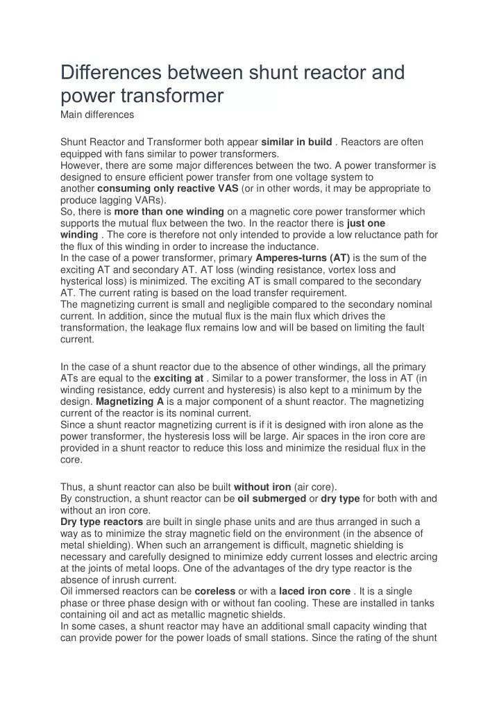
However, there are some major differences between the two. A power transformer is designed to ensure efficient power transfer from one voltage system to another consuming only reactive VAS (or in other words, it may be appropriate to produce lagging VARs).<br><br>

E N D
Differences between shunt reactor and power transformer Main differences Shunt Reactor and Transformer both appear similar in build . Reactors are often equipped with fans similar to power transformers. However, there are some major differences between the two. A power transformer is designed to ensure efficient power transfer from one voltage system to another consuming only reactive VAS (or in other words, it may be appropriate to produce lagging VARs). So, there is more than one winding on a magnetic core power transformer which supports the mutual flux between the two. In the reactor there is just one winding . The core is therefore not only intended to provide a low reluctance path for the flux of this winding in order to increase the inductance. In the case of a power transformer, primary Amperes-turns (AT) is the sum of the exciting AT and secondary AT. AT loss (winding resistance, vortex loss and hysterical loss) is minimized. The exciting AT is small compared to the secondary AT. The current rating is based on the load transfer requirement. The magnetizing current is small and negligible compared to the secondary nominal current. In addition, since the mutual flux is the main flux which drives the transformation, the leakage flux remains low and will be based on limiting the fault current. In the case of a shunt reactor due to the absence of other windings, all the primary ATs are equal to the exciting at . Similar to a power transformer, the loss in AT (in winding resistance, eddy current and hysteresis) is also kept to a minimum by the design. Magnetizing A is a major component of a shunt reactor. The magnetizing current of the reactor is its nominal current. Since a shunt reactor magnetizing current is if it is designed with iron alone as the power transformer, the hysteresis loss will be large. Air spaces in the iron core are provided in a shunt reactor to reduce this loss and minimize the residual flux in the core. Thus, a shunt reactor can also be built without iron (air core). By construction, a shunt reactor can be oil submerged or dry type for both with and without an iron core. Dry type reactors are built in single phase units and are thus arranged in such a way as to minimize the stray magnetic field on the environment (in the absence of metal shielding). When such an arrangement is difficult, magnetic shielding is necessary and carefully designed to minimize eddy current losses and electric arcing at the joints of metal loops. One of the advantages of the dry type reactor is the absence of inrush current. Oil immersed reactors can be coreless or with a laced iron core . It is a single phase or three phase design with or without fan cooling. These are installed in tanks containing oil and act as metallic magnetic shields. In some cases, a shunt reactor may have an additional small capacity winding that can provide power for the power loads of small stations. Since the rating of the shunt
reactor is normally based on the rating of the MVAr, this additional substation load VA must be taken into account when designing the reactor for such applications. Shunt reactors are used in high voltage systems to compensate for the capacitive generation of long overhead lines or extensive cable networks. The reasons for using shunt reactors are mainly two The first reason is to limit overvoltages and the second reason is to limit the transfer of reactive power in the network. If the transfer of reactive power is minimized ie reactive power being balanced in the different parts of the networks, a higher level of active power can be transferred into the network. Reactors to limit overvoltages are the most necessary in low power systems, that is to say when the to short-circuit power of the network is relatively low. The increase in voltage in a system due to capacitive generation is: ΔU (%) = QC x 100 / S sh.c or: Qc is the capacitive input of reactive energy on the network S sh.c is the short-circuit power of the network With the increase in the short-circuit power of the network, the increase in voltage will be less and the need for compensation to limit overvoltages will be less accentuated.
shunt reactor Reactors to achieve reactive power balance in the different parts of the network are most needed in heavily loaded networks where new lines cannot be built for environmental reasons. The reactors for this purpose are mainly thyristor controlled in order to quickly adapt to the reactive power required. Especially in industrial areas with arc furnaces the demand for reactive power fluctuates between each half cycle. In such applications, there are usually combinations of:
1. Thyristor Controlled Reactors ( TCR ) and 2. Switched thyristor capacitor banks ( TSC ). These elements make it possible to both absorb and generate reactive power according to the momentary demand. </ P> Four legged reactors can also be used for quenching the secondary are single phase reclosing in long transmission lines. Since there is always a capacitive coupling between the phases, this capacity will give a current maintaining the buckling, a secondary arc. By adding a single-phase reactor in the neutral, the secondary arc can be extinguished and the single-phase auto-reclosing successful.