Download
1 / 16
160 likes | 163 Views
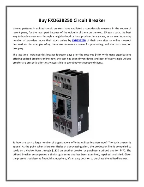
BCH Electric is one of Indiau2019s oldest and respected LV Switchgear manufacturer with world-class manufacturing facilities, pan-India distribution network and a wide product portfolio. Our decades of operations in Indian LV Switchgear market has helped us understand that Indian Industrial conditions are one of the harshest and most demanding in nature. for more info visit our website - https://bchindia.com/product/moulded-case-circuit-breakers-resilient-mccb/

E N D
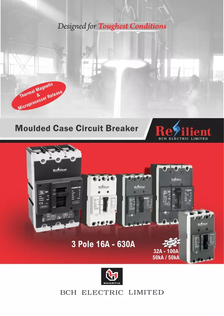
Designed for Toughest Conditions Thermal Magnetic Microprocessor Release & Moulded Case Circuit Breaker New 3 Pole 16A - 630A 32A - 100A 50kA / 50kA
c o n t e n t c o n t e n t Description Page S/N 01 Resilient MCCB : Overview 01-04 01-04 Technical Specification & Ordering Codes 02 05-07 05-07 03 Accessories 08 08 Tripping curves and ambience correction graphs 04 09-11 09-11 05 Installation dimension 12-14 12-14 Engineered BCH Electric is one of India’s oldest and respected LV Switchgear manufacturer with world-class manufacturing facilities, pan-India distribution network and a wide product portfolio. Our decades of operations in Indian LV Switchgear market has helped us understand that Indian Industrial conditions are one of the harshest and most demanding in nature. And we know the importance of a device which seamlessly, effortlessly and quite reliably delivers the best performance in varied applications under these harsh Indian conditions. Presenting to you the range of MCCB, available in three frame sizes 100A, 250A & 630A with standard and high Resilient performance variants. As the name Resilient implied, the product is designed and tested to perform excellently in harsh Indian conditions. Design excellence Remarkable performance Superior flexibility Reliability 01
Offers Remarkable Performance Tested for 50°C Ambience • We understand Indian conditions well, so the entire range of Resilient MCCB is tested for rated performance at 50°C. • upto 4% depending on the rating. With every 5 C dip in temperature, breaker can be uprated 0 Excellent Electrical / Mechanical Life • Electrical life upto 10000 cycles and Mechanical life upto 25000 cycles, Resilient MCCBs are designed for longer life and reliability. 25000 16000 8000 High Performance Compact Size • Resilient MCCB offers 50 kA Short circuit breaking capacity in smallest frame size of 75 X 130 X 60 mm (WxHxD). Outstanding Current Limiting Performance • Owing to a salient U shaped terminal and fast acting mechanism, Resilient MCCB offers excellent current limiting performance Designed for a very low level of let • through energy, Resilient MCCBs provides not only safety of installation but also reduces stress on downstream equipments KA Prospective Peak A Conventional MCCB Resilient MCCB B C 02
Offers Flexibility Flexibility of Installation 0 0 • Resilient MCCBs can be installed in any orientation i.e. vertical as well as horizontal orientation. +90 -90 0 0 Line Load Interchangeability Load Line • The entire range of Resilient MCCB is suitable for line load interchangeability, with unmarked terminals Load Line Thermal Flexibility T IR • Adjustable overload protection : Upto 70 % to 100 % with Thermal Magnetic Release 40% to 100% with Microprocessor Release (LSIG) MIN MAX Ii I Unbeatable Flexibility of Accessory Mounting • Resilient MCCB is one of its kind to have flexibility to install Click UV & Shunt Release together at a time for Frame 1 & Frame 2. • Universal accessory mounting for UV Release, Shunt Release, Trip Alarm & Auxiliary switch for Frame 1 & Frame 2. • All accessories can be field fitted, with no need for dismounting breaker. 03
Offers Reliability IEC 60947 International Standards Entire range of Resilient MCCB is tested and certified as per • IS / IEC 60947-2. Resilient MCCB also carries CE mark. • Suitability for Isolation • Resilient Range of MCCB is suitable for positive isolation. • Ensures complete safety of operator and installation. Isolation of Accessories • Internal accessory mounting chamber is isolated from main mechanism for safety of installation. Accessory must be mounted in TRIP condition. • Rotary handle is lockable in OFF condition to prevent any • unintended interventions to ensure operator safety. N O P I R TF F O T E S E R 6-7 MAX. Safety of Installation • Finger proof terminal. Constructional features Offers Design Excellence The Resilient MCCB is meticulously designed to incorporate necessary design features for superlative performance Unique Design for Controlled exhaust of ARC to minimize safety perimeter & ground surface Inherent Contact System Design to provide wiping effect between Contacts for self-cleaning action Use of special ABLATIVE material generates gases to suppress ARC PLASMA & Quench ARC Maximized Contact Repulsion forces with U-Shape design for high ARC interruption capacity Bimetal senses Overload protection Electro Magnet senses Short Circuit Protection Sectional View of Thermal Magnetic MCCB 04
Technical Specifications Type FRAME RS F1 Features Conformance to Standards No. of Poles Rated Operational Voltage(U ) - (V) Rated Insulation Voltage(U ) - (V) Rated Impulse withstand Voltage(Uimp) - (kV) Rated Current (I ) (A) e Ultimate Breaking Capacity(I ) at 415V (kA) Service Breaking Capacity(I ) - (% of I ) Suitability for Isolation Utilization Category Electrical Life - Cycles Mechanical Life - Cycles IS/IEC60947 - 2 3 415 690 6 e i 16, 20, 25, 32, 40, 50, 63, #80, #100 15 100 Yes A 6000 25000 10** 75 Yes A 5000 25000 30 50 Yes A 6000 25000 cu cs cu Protection against Over Current (Trip Unit) Thermal (Fixed / Adjustable) Magnetic Terminal Cable Capacity Dimensions - (mm) WxHxD Weight - (Kg) Operating Temp Range - °C Reference Temperature - °C Fixed Fixed 50 mm 75X130X60 0.81 / 0.89* -5 to +50 50 Fixed Fixed 50 mm 75X130X60 0.81 / 0.89* -5 to +50 50 Adjustable (0.7 - 1.0) In Fixed 50 mm 75X130X60 0.81 / 0.89* -5 to +50 50 2 2 2 Accessories - INTERNAL Auxiliary (2C/O) Aux / Alarm (1C/O + 1 C/O) Shunt Release Under Voltage Release (UVR) Yes Yes Yes Yes Yes Yes Yes Yes Yes Yes Yes Yes Accessories - EXTERNAL Rotary Operating Handle (Extended) Phase Barriers Spreaders / Terminal Extensions DIN Rail Mounting Kit Yes Yes Yes Yes Yes Yes Yes Yes Yes Yes Yes Yes *Weight along with spreader link # Spreader link included from 80A & 100A in F1 MCCB and 200A & 250A in F2 MCCB ** With RAL-7035 (Light Grey) front facia, rest all other ratings are RAL-7016 (Dark Grey) front facia Range & Ordering Codes For Frame 1 (Ith= 100 A) XF E 100 G* V: 50 kA 100: 100A 80: 80A 63: 63 A 50: 50A 40:40A 32: 32A 25: 25A 20: 20A 16: 16A P : Ics 100% of Icu G : Ics 75% of Icu N : Ics 50% of Icu L: 36 kA H: 30 kA S: 25 kA N: 15 kA E: 10 kA * add a suffix V ( PV and NV) for variable thermal variant For MCCB of any other rating, please contact nearest sales office 05
RH F1 RS F2 RH F2 IS/IEC60947 - 2 3 415 690 8 IS/IEC60947 - 2 3 415 690 8 125, 160, #200, #250 25 100 Yes A 5000 12000 IS/IEC60947 - 2 3 415 690 8 125, 160, #200, #250 800 8 16, 20, 25, 32, 40, 50, 63, #80, #100 32A to #100A 50 100 Yes A 10000 25000 25 100 Yes A 8000 25000 36 50 Yes A 8000 25000 50 50 Yes A 8000 25000 36 50 Yes A 5000 12000 36 75 Yes A 8000 12000 36 100 Yes A 8000 12000 50 50 Yes A 8000 12000 50 100 Yes A 8000 12000 Adj. (0.7-1.0) In Fixed 50 mm 75X130X60 0.83 / 0.91* -5 to +55 50 Adj. (0.8-1.0) In Fixed 120 mm 105x160x81 2.2 / 2.6* -5 to +50 50 Adj. (0.7-1.0) In Fixed 50 mm 75X130X60 0.81 / 0.89* -5 to +50 50 Adj. (0.7-1.0) In Fixed 50 mm 75X130X60 0.81 / 0.89* -5 to +50 50 Adj. (0.7-1.0) In Fixed 50 mm 75X130X60 0.81 / 0.89* -5 to +50 50 Adj. (0.8-1.0) In Fixed 120 mm 105x160x81 2.2 / 2.6* -5 to +50 50 Adj. (0.8-1.0) In Fixed 120 mm 105x160x81 2.2 / 2.6* -5 to +50 50 Adj. (0.8-1.0) In Fixed 120 mm 105x160x81 2.2 / 2.6* -5 to +50 50 Adj. (0.8-1.0) In Fixed 120 mm 105x160x81 2.2 / 2.6* -5 to +50 50 Adj. (0.8-1.0) In Fixed 120 mm 105x160x81 2.2 / 2.6* -5 to +50 50 2 2 2 2 2 2 2 2 2 2 Yes Yes Yes Yes Yes Yes Yes Yes Yes Yes Yes Yes Yes Yes Yes Yes Yes Yes Yes Yes Yes Yes Yes Yes Yes Yes Yes Yes Yes Yes Yes Yes Yes Yes Yes Yes Yes Yes Yes Yes Yes Yes Yes Yes Yes Yes Yes Yes Yes Yes Yes Yes Yes Yes Yes Yes Yes Yes Yes No Yes Yes Yes No Yes Yes Yes No Yes Yes Yes No Yes Yes Yes No Yes Yes Yes No For Frame 2 (Ith= 250 A) 250: 250 A 250 : 250A XF2 H 250 PV* PV : Ics 100% of Icu H: 50 kA GV : Ics 75% of Icu 200 : 200A N: 36 kA NV : Ics 50% of Icu 160 : 160A E: 25 kA 125 : 125A * Variable thermal setting available by default For MCCB of any other rating, please contact nearest sales office 06
MTU-LSIG Neutral Protection On/Off Feature Thermal Memory On/Off Feature Choice of 50% / 100% Neutral Selection Choice of class 5 / class 10 Protection Technical Specifications Type RH - TMTU RH - LSIG FRAME F3 F3 Features Ref Standards No. of Poles Rated Operational Voltage(U ) - (V) Rated Insulation Voltage(U) - (V) Rated Impulse withstand Voltage(Uimp) - (kV) Rated Current (I ) - (A) e Ultimate Breaking Capacity(I ) at 415V (kA) Service Breaking Capacity(I ) - (% of I ) Suitability for Isolation Utilization Category Electrical Life - Cycles Mechanical Life - Cycles IS/IEC60947 - 2 3 415 800 8 320 , 400 , 500 , 630 # # 36 100 Yes A 5000 12000 IS/IEC60947 - 2 3 415 800 8 400 , 630 # e i # # # 50 100 Yes A 5000 12000 36 100 Yes A 5000 12000 50 100 Yes A 5000 12000 cu cs cu Protection against Over Current (Trip Unit) Thermal - Adjustable/Microprocessor Magnetic - Adjustable/Microprocessor Short Circuit Delay Earth Fault Setting Earth Fault Delay Instantaneous Setting Thermal - Adjustable (0.8 - 1.0) In Magnetic - Adjustable (6.0 - 10.0) In N/A N/A N/A N/A N/A Microprocessor (0.4 - 1.0) In Microprocessor (Off - 1.5 - 10.0) Ir 50 - 500 ms Off - 0.2 - 0.55 In 50 - 500 ms 12 Ir Available Pre Trip Alarm Indication 2 240, 185*2 mm 140x261x103.5 Terminal Cable Capacity Dimensions - (mm) WxHxD Weight - (Kg) Operating Temp Range - °C Reference Temperature - °C 2 185, 240, 150*2, 185*2 mm 140x261x103.5 5.6 / 6.48*(400A) and 5.8 / 7.0*(630A) -5 to + 55 50 6.35 / 7.22*(400A) and 6.60 / 7.8*(630A) -5 to + 55 50 Accessories - INTERNAL Auxiliary (3C/O)$ Auxiliary (2C/O) Aux / Alarm (1C/O + 1 C/O) Shunt Release Under Voltage Release (UVR) Yes Yes Yes Yes Yes Yes Yes Yes Yes Yes Accessories - EXTERNAL Rotary Operating Handle (Extended) Phase Barriers Spreaders / Terminal Extensions Yes Yes Yes Yes Yes Yes * Weight along with spreader link $ Auxiliary (2 C/O) and Aux. / Alarm (1 C/O + 1 C/O) can be mounted simultaneously # 6 Nos. Spreader link available in standard packing Range & Ordering Codes For Frame 3 (Ith= 630 A) X 3 F H 630 P* 630: 630A 500: 500A 400: 400A 320: 320A P : Ics 100% of Icu H: 50 kA N: 36 kA * add a suffix V ( PV ) for variable thermal variant & suffix E ( PE ) for Microprocessor Release with LSIG protection For MCCB of any other rating, please contact nearest sales office 07
Internal Accessories Compliance to : IS/IEC 60947-2 Universal accessories mounting Alarm / Auxiliary & Auxiliary: Switch Undervoltage Release Shunt Release • Auxiliary Switch - 2 C/O ( For all Frames). It is possible to provide upto 3 C/O switch along with Shunt / UV Release in F3 MCCB • Wide Operating voltage range : 220 - 415 V AC/DC • Operating Voltage : 240 V AC, 415 V AC • Pick up consumption : 230V AC <16 VA (For Frame 1 & 2) <20 VA (For Frame 3) & 440V AC <54 VA (For Frame 1 & 2) <75 VA (For Frame 3 MCCB) • UV Release operates & opens the MCCB in between 70% to 35% of Ue • Trip Alarm & Auxiliary - Auxiliary (1 C/O) + Alarm(1 C/O) • Rating for Utilization categories : - At 250V : AC15 - 2A, DC13 - 0.2A • At 30% of Ue it is not possible to close the MCCB • Response time : <20 ms • Ith=5A, Ue=230V, Ie=2A for AC15 Duty • Operates at 70% to 110% of Ue • At 85% of Ue it is possible to close the MCCB • Auxiliary Switch operates in normal ON/OFF operation simultaneously with main contacts. Alarm operates only when the breaker trips • With Shunt Release energized not possible to Switch ON the MCCB • Sealed consumption : <5 VA Rotary Operating Handle - Extended • Handle - Pistol type grip • Door interlocking in ON condition • Defeat feature for door interlock • Adjustable shaft length at customer site • Upto three Padlocks (ɸ6mm for F1/F2 & ɸ8mm for F3) possibility in OFF condition • Ingress protection when mounted in enclosure : Frame 1 & Frame 2 - IP42 Frame 3 - IP54 • Minimum depth required to mount ROH in panel Type Type Product Din Rail Product Rating F1 F1 F2 F3 F1 F1 F2 F2 Rating Cat Code F1DIN F1ROHE F2ROHE F3ROHE ACMF1TP100 ACMF1TP100-3T ACMF2TP160-T Cat Code Remarks Extended Rotary Handle (6Nos) for F1 MCCB (3Nos) for F1 for one side (6Nos) for F2-160/125A MCCB Type Product Rating 220V - 415V F1 220V - 415V 220V - 415V 240V ac 240V ac 240V ac 415V ac 415V ac 415V ac Cat Code XFSHT220V XF2SHT220V XF3SHT220V Shunt Release F2 F3 F1 F2 F3 F1 F2 F3 (6Nos) for F2-250/200A MCCB - Standard (6Nos) for F2 MCCB - Optional (wider) ACMF2TP250-T ACMF2TP250 Extended Terminals* F2 F2 F3 F3 XFUV240VA XF2UV240VA XF3UV240VA External Accessories ACMF2TP250-3T ACMF3TP400 ACMF3TP400-3T (3Nos) for F2 for one side - Optional (wider) (6Nos) for 400A F3 MCCB Internal Accessories Under Voltage Release (3Nos) for 400A F3 for one side *Dimension available on page # 12, 13 & 14 XFUV415VA XF2UV415VA XF3UV415VA XFALAX11 XFAX2 F3 F3 (6Nos) for 630A F3 MCCB ACMF3TP630 ACMF3TP630-3T (3Nos) for 630A F3 for one side F1PB F2PB F3PB F1EU3P F1 F2 F3 F1 Phase Barriers Alarm + Aux. Contacts Aux. Contacts 1 C/O + 1 C/O 2 C/O MCCB Enclosure F2 F2EU3P 08
Tripping Curves Frame 1 (≤ 100 A) 10000 10000 5000 5000 2000 2000 1000 1000 500 500 200 200 MAX. 20A MAX. 16A 100 100 50 50 20 10 20 10 MIN. 16A TIME (s) TIME (s) MIN. 20A 5 5 2 2 1 1 .5 .5 .2 .2 .1 .1 .05 .05 .02 .02 .01 .01 .005 .005 .002 .002 .001 .001 300 20 100 30 40 200 300 20 100 10 30 70 50 .7 4 40 200 5 2 10 .5 70 7 50 3 .7 4 1 5 2 .5 7 3 1 I / Ir I / Ir 10000 10000 5000 5000 2000 2000 1000 1000 MAX. (32A~50A) 500 500 MAX. 25A 200 200 MAX. (63A~100A) 100 100 50 50 20 10 20 10 TIME (s) MIN. 25A TIME (s) 5 5 MIN. (63A~100A) 2 2 1 1 MIN. (32A~50A) .5 .5 .2 .2 .1 .1 .05 .05 .02 .02 .01 .01 .005 .005 .002 .002 .001 .001 300 20 100 30 40 200 10 70 300 50 .7 4 20 100 30 5 2 40 200 .5 7 3 1 10 70 50 .7 4 5 2 .5 7 3 1 I / Ir I / Ir 09
Tripping Curves Frame 2 (≤ 250 A) 10000 10000 5000 5000 2000 2000 1000 1000 500 500 MAX. (160~200A) 200 200 MAX. 125A 100 100 50 50 20 10 20 10 TIME (s) TIME (s) MIN. 125A 5 5 2 2 1 1 MIN. (160~200A) .5 .5 .2 .2 .1 .1 .05 .05 .02 .02 .01 .01 .005 .005 .002 .002 .001 .001 300 20 100 30 40 200 10 70 50 .7 4 5 2 .5 7 3 1 300 20 100 30 40 200 10 70 50 .7 4 5 2 .5 7 3 1 I / Ir I / Ir Ambience correction graph 10000 5000 2000 1000 500 200 MAX. 250A 100 50 20 10 TIME (s) 5 2 MIN. 250A 1 .5 .2 .1 .05 .02 .01 .005 .002 .001 300 20 100 30 40 200 10 70 50 .7 4 5 2 .5 7 3 1 I / Ir 10
Tripping Curves Frame 3 (≤ 630 A) 11
Frame 1 – Installation Dimensions BREAKER MOUNTING PROCEDURE AND MOUNTING DIMENSIONS FOR FRONT CONNECTION (FC) : F1 MCCB WITH TERMINAL PLATE SET (ACMF1TP100) M3 x60 Combined Slot Pan Head Screw for Breaker Mounting (2 Nos Diagonally) Equals to 4 MCB's width in Distribution Boxes 72 116 110 130 45 29 = = = = 25 237 185 162 M8 x 12.5 Combined SlotPan Head Terminal Screw & Terminal Washer (6 Nos. each) 25 60 69.3 72.5 25 25 69 75 85 35 35 93 24.8 Frame 1 – Rotary Handle Installation Dimensions F1ROHE CENTERALLY PLACED CUT OUT OF EXTENDED - ROH FOR ANY DIRECTION MOUNTING OF BREAKER IN PANEL : 2 NOS. CENTERALLY LOCATED HOLES FOR HANDLE MOUNTING M3 TAPPING FOR BREAKER MOUNTING (2 NOS.) 45° ROTARY OPERATING HANDLE : EXTENDED - ROH EXTENDED - ROH 30 =110= 4.2 =45= =25= CUT OUT ON PANEL DOOR FOR HANDLE MOUNTING 130 min. / 275 max. 130 min. / 275 max. 12
Frame 2 – Breaker Installation Dimensions BREAKER MOUNTING PROCEDURE AND MOUNTING DIMENSIONS FOR FRONT CONNECTION (FC) : M4 x82 Combined Slot Pan Head Screw for Breaker Mounting (2 Nos Diagonally) 160 64.7 122 142 37 = = = = 20.3 M8 x 22 Allen Head Terminal Screw & Terminal Washer (6 Nos. each) 81 35 91.3 35 35 94.2 105 113.3 26.5 With Standard Terminals With Optional Terminals Frame 2 – Rotary Handle Installation Dimensions CENTERALLY PLACED CUT OUT OF EXTENDED - ROH FOR ANY DIRECTION MOUNTING OF BREAKER IN PANEL : ROTARY OPERATING HANDLE : EXTENDED - ROH M4 TAPPING FOR BREAKER MOUNTING (2 NOS. DIAGONALLY) ON MOUNTING PLATE 2 NOS. CENTERALLY LOCATED HOLES FOR HANDLE MOUNTING 45° 30 =122= 4.2 156 min. / 298 max. =45= =35= CUT OUT ON PANEL DOOR FOR HANDLE MOUNTING F2ROHE 13
Frame 3 – Breaker Installation Dimensions BREAKER MOUNTING PROCEDURE AND MOUNTING DIMENSIONS FOR FRONT CONNECTION (FC) : M5X110 COMBINED SLOT PAN HEAD SCREW FOR BREAKER MOUNTING (4 NOS.) 55.2 235.8 107 261 222 392 342 444 43.5 103.5 122 132 43.5 43.5 M10 SOCKET HEAD SCREW, SPRING WASHER AND PLAIN WASHER (6 NOS. EACH) 140 163 60 60 161 28.8 Frame 3 – Rotary Handle Installation Dimensions CENTERALLY PLACED CUT OUT OF EXTENDED - ROH FOR ANY DIRECTION MOUNTING OF BREAKER IN PANEL : ROTARY OPERATING HANDLE : EXTENDED - ROH 14
Visit us at : www.bchindia.com Corporate Office : 1105, New Delhi House, 27, Barakhamba Road, New Delhi - 110 001 Tel. : 91-11-23316029/3610/6539/43673100 Fax : 91-11-23715247 U31103WB1965PLC026427, Customercare No. 1800-103-9262, E-mail : marketing@bchindia.com CIN : Block 1E, 216, Acharya Jagadish Chandra Bose Road, Kolkata - 700 017 Registered Office : 20/4, Mathura Road, Faridabad - 121 006 (Haryana) Tel. : 0129-4063000/4293000 Fax : 0129-2304016 Works 1 : 64-68, Sector-7, IIE, Pant Nagar, Rudrapur, Udham Singh Nagar - 263 153 (Uttrakhand) Tel. : 05944-250214/16 Fax : 05944-250215 Works 2 : Sales Offices : Ahmedabad 103, Aaron, Nr. SBI Laghuudyog branch, Behind Sakar-1, Gandhigram Railway Station, Ellis bridge, Ahmedabad- 380 006 Tel. : 079-26589719 E-mail : ahmedabad@bchindia.com Dehradun 8, Co-operative Industral Estate, Patel Nagar, Dehradun-248001 E-mail : dehradun@bchindia.com Bangalore B.M.H. Complex, 2nd Floor, No. 22, Kengal Hanumanthiah Road, Bangalore - 560 027 Tel. : 080-22273478/41144878/41144879 Fax : 080-22236759 E-mail : bangalore@bchindia.com Chandigarh SCO 121-22-23, 1st Floor, Sector 34-A, Chandigarh - 160 022 Tel. : 0172-5078957/2666122 Fax : 0172-5049905 E-mail : chandigarh@bchindia.com Chennai Flat No. 3A, 3rd Floor, Sree Apartments, No.508, TTK Road, Alwarpet, Chennai 600 018 Tel.: 044-24337046, 24337047 Fax : 044-24337047 E-mail : chennai@bchindia.com Coimbatore 87, Dr. Nanjappa Road, Coimbatore - 641 018 Tel. : 0422-2305311 Fax : 0422-2302599 E-mail : coimbatore@bchindia.com Faridabad 20/4, Mathura Road, Faridabad - 121 006 (Haryana) Telfax. : 0129-2304016 E-mail : faridabad@bchindia.com Hyderabad 1-8-303/48/13/102, Arya One, 2nd Floor, P. G. Road, Secunderabad - 500 003 Tel. : 040-66206263/27890306 Fax : 040-66207273 E-mail : hyderabad@bchindia.com Indore 330-331, Indraprastha Tower, 3rd Floor, 6, M.G. Road, Indore - 452 001 Tel. : 0731-2510011 Fax : 0731-2510012 E-mail : indore@bchindia.com Jaipur 25, Hathroi, Gopalbari, Jaipur - 302 001 Tel. : 0141-5104521 Fax : 0141-2363521 E-mail : jaipur@bchindia.com Jamshedpur 3rd Floor, Aastha Trade Centre, 'Q' Road, Bistupur, Jamshedpur - 831 001 Tel. : 0657-2321097/2321481 E-mail : jamshedpur@bchindia.com Kolkata Block 1E, 216, Acharya Jagadish Chandra Bose Road, Kolkata - 700 017 Tel. : 033-22871728 E-mail : kolkata@bchindia.com Lucknow Madan Plaza, 3rd Floor, 14, Station Road, Lucknow - 226 001 Tel. : 0522-4025597/4025997 Fax : 0522-4025697 E-mail : lucknow@bchindia.com Ludhiana S.C.O.- 18, 2nd Floor, Feroze Gandhi Market, Ludhiana - 140 001 Tel. : 0161-5021807/5022808 Fax : 0161-5021807 E-mail : ludhiana@bchindia.com Mumbai A-151, Mittal Tower, Nariman Point, Mumbai - 400 021 Tel. : 022-22822947/22850162 Fax : 022-22822858 E-mail : mumbai@bchindia.com Nagpur Flat No. T/12, 3rd Floor Baldeo Apartment, Behind Railway Station, Bajeria Nagpur (M.S.) - 440018 E-mail : nagpur@bchindia.com New Delhi 801, Akash Deep Building, 26A, Barakhamba Road, New Delhi - 110 001 Tel. : 011-23313878/66307065 Fax : 011-23739230 E-mail : delhi@bchindia.com Pune 8, Sarosh Bhavan, 16-B/1, Dr. Ambedkar Road, Pune - 411 001 Tel. : 020-26052590 Telefax : 020-26135224 E-mail : pune@bchindia.com Raipur 2nd Floor, Building No. B-234, Indira Gandhi Vyavasayik Parisar, Pandri, Raipur - 492 004 Tel. : 0771-4020213 Fax : 0771-2582680 E-mail : raipur@bchindia.com Trichy Kingstone Park, 2nd Floor, 19/1, Puthur High Road, Ramalinga Nagar, Trichy - 620 017 Tel. : 0431-4040497 E-mail : trichy@bchindia.com Vadodara 301, Third Floor, “Florence Classic”, 10, Ashapuri Co-Op. Hsg. Soc. Ltd., Opp. VUDA Housing, Near Cow Circle, Akota, Vadodara - 390 020 Tel. : +91-265-6548444/2345068/2345069 Telefax : 0265-2345068, E-mail : vadodara@bchindia.com Other Branch Locations Bhubaneswar : bhubaneswar@bchindia.com, Cochin : cochin@bchindia.com, Gurgaon : gurgaon@bchindia.com, Guwahati : guwahati@bchindia.com,Hospet : hospet@bchindia.com, Hubli : hubli@bchindia.com, Madurai : madurai@bchindia.com, Vishakapatnam : vizag@bchindia.com, Surat : surat@bchindia.com Switch gear control gear Product/MCCB/issue 2.1/May. 2017 Resident Engineer Locations Baddi Bardhman Bhilai Bhubaneswar Cochin Dehradun Durgapur Madurai Muzaffarnagar Nagpur Nashik Patna Puducherry Rajkot Rajahmundry Salem Surat Udaipur Vapi Vishakhapatnam Warangal Gurgaon Haridwar Hubli Hospet Jodhpur Kakinada Kota Since product improvement is a continuous process, the data furnished in this brochure may undergo revision without prior notice.