Download
1 / 6
60 likes | 542 Views
Earthquake Resistant Features in Buildings. Dr. K. S. Nanjunda Rao. Shock Table Test Facility for Evaluating Earthquake Resistant Features in Buildings. Research & Development Indigenous design and fabrication of test facility Novel earthquake resistant features for masonry buildings

E N D
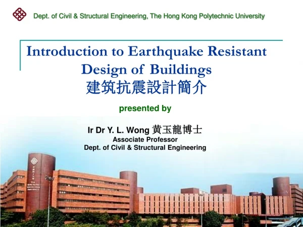
Earthquake Resistant Features in Buildings Dr. K. S. Nanjunda Rao
Shock Table Test Facility for Evaluating Earthquake Resistant Features in Buildings • Research & Development • Indigenous design and fabrication of test facility • Novel earthquake resistant features for masonry buildings • Simulating failure patterns same as those observed in buildings after an earthquake Peak table acceleration 1.1g Pendulum (1.8m length & 600kg mass Max. swing 400) Masonry Building Models Rebound beam Table acceleration response for a swing angle of 300 Table (payload 5000kg) Fund. Freq. 90Hz containment reinforcement with link Corner containment reinforcement with triangular link Data acquisition system
Response after 5 shocks Behavior of building models after 13 shocks One fourth scale models Model 1 Response at top of cross wall Model 1 (ERF as per IS 4326:1993) Model 2 (ERF as per IS 4326:1993 plus additional R C band at Sill level and Containment reinforcement Model 2 Response at top of cross wall
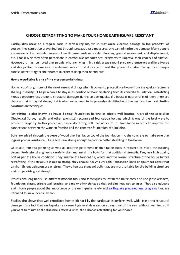
Shock Table Test Facility Shock table test facility for evaluating seismic performance of buildings was designed and constructed. The table is of size 3.5m by 2.5m and is supported on 4 wheels with ability to move horizontally in one direction on rails. The table can be subjected to shocks through a swinging pendulum of 600kg mass with provision to increase the mass up to 1000kg. On the side of the table opposite to the pendulum, provision is made to generate a reverse shock through a reaction beam. The impulse force that can be given to the table can be varied by changing the swing angle of the pendulum, mass of the pendulum, the material to which the pendulum impacts. The reverse force to the table can also be varied by changing the gap between the table and the reaction beam before the start of the test. The photograph shows two brick masonry building models with different earthquake resistant features on the shock table with instrumentation to measure the table motion and the response of the building models.
CONCEPT OF ‘CONTAINMENT REINFORCEMENT’ It is well known that most of the structures tend to undergo large deformations in the event of a strong earthquake. If the stresses caused due to lateral forces experienced by the structures exceed its strength, the structure yields, if it is ductile. If the structure is brittle, as in the case of un-reinforced masonry, it will suffer brittle failure. The pattern of failure of masonry buildings during an earthquake makes it clear that the prevention of sudden flexural failure of masonry wall is critical to ensure an earthquake resistant masonry structure. Again, since flexural tension can occur on both faces of the wall due to reversal of stresses during an earthquake, there is a need to provide ductile reinforcement on both faces. This can be accomplished by placing vertical reinforcement either on the surface or close to the surface and surrounding the wall, which is termed as “containment reinforcement”. For the containment reinforcement to be effective, it is essential for it to remain hugged to the wall at all times during an earthquake and to deform along with the masonry. In order to meet this objective the vertical reinforcements on either face of the wall have to be connected to each other, by horizontal ties/links passing through the bed joints of masonry. These horizontal ties along with the mortar in the bed joints will ensure strain compatibility between vertical reinforcement and the masonry. Earlier study on the flexure of masonry beams with longitudinal reinforcement wrapped round the beam with links through the bed joints connecting the top and bottom reinforcement has shown substantial ductility with multiple cracks before failure. Containment reinforcement is not primarily intended to increase the lateral strength of the wall, but to permit large ductile deformation and to avoid total collapse. In other words, containment reinforcement will act as main energy absorbing element of the wall which otherwise has poor energy absorption capacity.
Containment reinforcement Link/tie Masonry with containment reinforcement and links/ties connecting them through bed joints.