Download
1 / 7
70 likes | 102 Views
This paper deals with a three-phase two-stage grid tied SPV (solar photo-voltaic) system. The first stage is a boost converter, which serves the purpose of MPPT (maximum power point tracking) and feeding the extracted solar energy to the DC link of the PV inverter, whereas the second stage is a two-level VSC (voltage source converter) serving as PV inverter which feeds power from a boost converter into the grid. The proposed system uses an adaptive DC link voltage which is made adaptive by adjusting reference DC link voltage according to CPI (common point of interconnection) voltage. The adaptive DC link voltage control helps in the reduction of switching power losses. A feed forward term for solar contribution is used to improve the dynamic response. The system is tested considering realistic grid voltage variations for under voltage and over voltage. The performance improvement is verified experimentally. The proposed system is advantageous not only in cases of frequent and sustained under voltage (as in the cases of far radial ends of Indian grid) but also in case of normal voltages at CPI. The THD (total harmonics distortion) of grid current has been found well under the limit of an IEEE-519 standard.

E N D
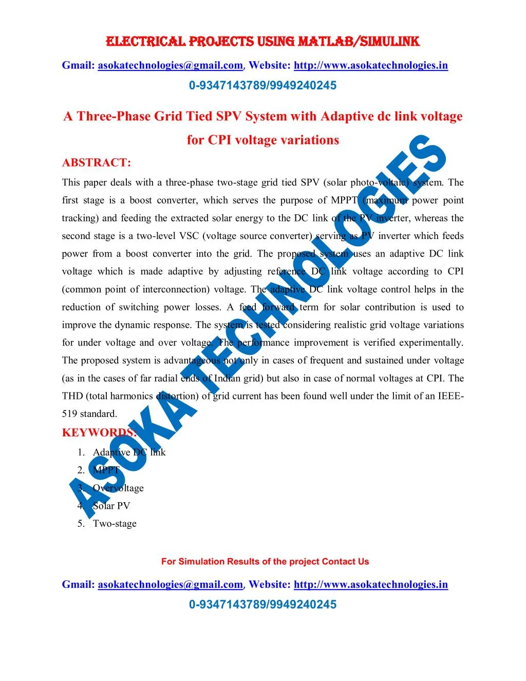
ELECTRICAL PROJECTS USING MATLAB/SIMULINK ELECTRICAL PROJECTS USING MATLAB/SIMULINK Gmail:asokatechnologies@gmail.com, Website: http://www.asokatechnologies.in 0-9347143789/9949240245 A Three-Phase Grid Tied SPV System with Adaptive dc link voltage for CPI voltage variations ABSTRACT: This paper deals with a three-phase two-stage grid tied SPV (solar photo-voltaic) system. The first stage is a boost converter, which serves the purpose of MPPT (maximum power point tracking) and feeding the extracted solar energy to the DC link of the PV inverter, whereas the second stage is a two-level VSC (voltage source converter) serving as PV inverter which feeds power from a boost converter into the grid. The proposed system uses an adaptive DC link voltage which is made adaptive by adjusting reference DC link voltage according to CPI (common point of interconnection) voltage. The adaptive DC link voltage control helps in the reduction of switching power losses. A feed forward term for solar contribution is used to improve the dynamic response. The system is tested considering realistic grid voltage variations for under voltage and over voltage. The performance improvement is verified experimentally. The proposed system is advantageous not only in cases of frequent and sustained under voltage (as in the cases of far radial ends of Indian grid) but also in case of normal voltages at CPI. The THD (total harmonics distortion) of grid current has been found well under the limit of an IEEE- 519 standard. KEYWORDS: 1.Adaptive DC link 2.MPPT 3.Overvoltage 4.Solar PV 5.Two-stage For Simulation Results of the project Contact Us Gmail:asokatechnologies@gmail.com, Website: http://www.asokatechnologies.in 0-9347143789/9949240245
ELECTRICAL PROJECTS USING MATLAB/SIMULINK ELECTRICAL PROJECTS USING MATLAB/SIMULINK Gmail:asokatechnologies@gmail.com, Website: http://www.asokatechnologies.in 0-9347143789/9949240245 6.Three phase 7.Under voltage SOFTWARE: MATLAB/SIMULINK CIRCUIT DIAGRAM: Fig. 1. System configuration. For Simulation Results of the project Contact Us Gmail:asokatechnologies@gmail.com, Website: http://www.asokatechnologies.in 0-9347143789/9949240245
ELECTRICAL PROJECTS USING MATLAB/SIMULINK ELECTRICAL PROJECTS USING MATLAB/SIMULINK Gmail:asokatechnologies@gmail.com, Website: http://www.asokatechnologies.in 0-9347143789/9949240245 CONTROL SYSTEM Fig. 2. Block diagram for control approach. For Simulation Results of the project Contact Us Gmail:asokatechnologies@gmail.com, Website: http://www.asokatechnologies.in 0-9347143789/9949240245
ELECTRICAL PROJECTS USING MATLAB/SIMULINK ELECTRICAL PROJECTS USING MATLAB/SIMULINK Gmail:asokatechnologies@gmail.com, Website: http://www.asokatechnologies.in 0-9347143789/9949240245 EXPECTED SIMULATION RESULTS: Fig. 3. Simulated performance for, (a) change in solar insolation without feedforward for PV contribution, (b) change in solar insolation with feed forward for PV contribution, For Simulation Results of the project Contact Us Gmail:asokatechnologies@gmail.com, Website: http://www.asokatechnologies.in 0-9347143789/9949240245
ELECTRICAL PROJECTS USING MATLAB/SIMULINK ELECTRICAL PROJECTS USING MATLAB/SIMULINK Gmail:asokatechnologies@gmail.com, Website: http://www.asokatechnologies.in 0-9347143789/9949240245 (c) normal to under voltage (415 V to 350 V), (d) CPI voltage variation from normal to over voltage (415 V to 480 V). For Simulation Results of the project Contact Us Gmail:asokatechnologies@gmail.com, Website: http://www.asokatechnologies.in 0-9347143789/9949240245
ELECTRICAL PROJECTS USING MATLAB/SIMULINK ELECTRICAL PROJECTS USING MATLAB/SIMULINK Gmail:asokatechnologies@gmail.com, Website: http://www.asokatechnologies.in 0-9347143789/9949240245 CONCLUSION: A two-stage system has been proposed for three-phase grid connected solar PV generation. A composite InC based MPPT algorithm is used for control of the boost converter. The performance of proposed system has been demonstrated for wide range of CPI voltage variation. A simple and novel adaptive DC link voltage control approach has been proposed for control of grid tied VSC. The DC link voltage is made adaptive with respect to CPI voltage which helps in reduction of losses in the system. Moreover, a PV array feed forward term is used which helps in fast dynamic response. An approximate linear model of DC link voltage control loop has been developed and analyzed considering feed forward compensation. The PV array feed forward term is so selected that it is to accommodate for change in PV power as well as for CPI voltage variation. A full voltage and considerable power level prototype has verified the proposed concept. The concept of adaptive DC link voltage has been proposed for grid tied VSC for PV application however, the same concept can be extended for all shunt connected grid interfaced devices such as, STATCOM, D-STATCOM etc. The proposed system yields increased energy output using the same hardware resources just by virtue of difference in DC link voltage control structure. The THDs of the grid currents and voltages are found less than 5% (within IEEE-519 standard). The simulation and experimental results have confirmed the feasibility of proposed control algorithm. For Simulation Results of the project Contact Us Gmail:asokatechnologies@gmail.com, Website: http://www.asokatechnologies.in 0-9347143789/9949240245
ELECTRICAL PROJECTS USING MATLAB/SIMULINK ELECTRICAL PROJECTS USING MATLAB/SIMULINK Gmail:asokatechnologies@gmail.com, Website: http://www.asokatechnologies.in 0-9347143789/9949240245 REFERENCES: [1] M. Pavan and V. Lughi, “Grid parity in the Italian commercial and industrial electricity market,” in Proc. Int. Conf. Clean Elect. Power(ICCEP’13), 2013, pp. 332–335. [2] M. Delfanti, V. Olivieri, B. Erkut, and G. A. Turturro, “Reaching PV grid parity: LCOE analysis for the Italian framework,” in Proc. 22nd Int. Conf. Exhib. Elect. Distrib. (CIRED’13), 2013, pp. 1–4. [3] H.Wang and D. Zhang, “The stand-alone PV generation system with parallel battery charger,” in Proc. Int. Conf. Elect. Control Eng. (ICECE’10), 2010, pp. 4450–4453. [4] M. Kolhe, “Techno-economic optimum sizing of a stand-alone solar photovoltaic system,” IEEE Trans. Energy Convers., vol. 24, no. 2, pp. 511–519, Jun. 2009. [5] D. Debnath and K. Chatterjee, “A two stage solar photovoltaic based stand alone scheme having battery as energy storage element for rural deployment,” IEEE Trans. Ind. Electron., vol. 62, no. 7, pp. 4148–4157, Jul. 2015. For Simulation Results of the project Contact Us Gmail:asokatechnologies@gmail.com, Website: http://www.asokatechnologies.in 0-9347143789/9949240245