Download
1 / 25
250 likes | 451 Views
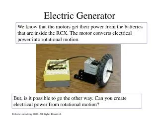
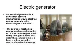
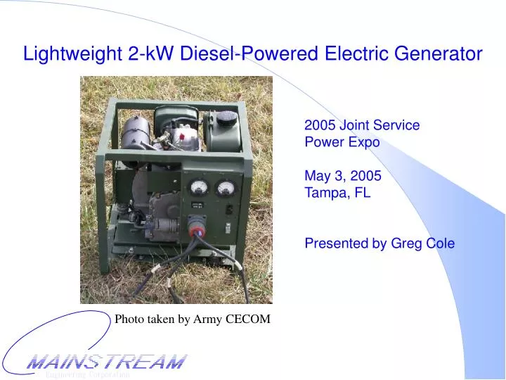
Lightweight 2-kW Diesel-Powered Electric Generator. 2005 Joint Service Power Expo May 3, 2005 Tampa, FL Presented by Greg Cole. Photo taken by Army CECOM. Mainstream Generator History. Engine Development (1991- ) Customer: U.S. Army RD&E Center (Natick)

E N D
Lightweight 2-kW Diesel-Powered Electric Generator 2005 Joint ServicePower ExpoMay 3, 2005Tampa, FLPresented by Greg Cole Photo taken by Army CECOM
Mainstream Generator History • Engine Development (1991- ) • Customer: U.S. Army RD&E Center (Natick) • Application: Small, diesel-powered, personal cooling system • Alternator Development (1994 - ) • Customer: U.S. Army Aberdeen / OST • Application: Miniature, multi-fueled generator • Results • Diesel-cycle is better than Rankine, Stirling, Brayton, and converted spark ignition (gasoline) • Mainstream designs and produces integrated, custom machines
2-kW Generator Requirements • Customer: Marine Corps System Command (MCSC) • Application: Team Portable Collection System (TPCS) • Project Philosophy: Commercial hardware, not Mil-Spec hardware • Goals: • Power is expected to exceed 1 kW @ 28 VDC • Desired weight is less than 50 lbs • Desired fuel is diesel
2-kW, 28-VDC Generator Evolution • Phase I – MCSC • Initial demonstration • 1.6-kW Generator: 42-lbs unmounted (14” x 11” x 16”) • Phase II – MCSC • Revised prototypes • 2-kW Generator: 48-lbs unmounted • 2-kW Generator: 65-lbs backpack mounted (18” x 17” x 20”) • Phase III – ONR • Two test units delivered to Army CECOM • 2-kW Generator: 80-lbs roll cage mounted (18” x 18” x 20”) • Phase III – MCSC • Additional test units similar to ONR units • Addresses issues identified during Army CECOM tests
Mainstream’s Generators • Integrated system designed for military applications • Alternator integrated into engine flywheel • resulting in a lighter system • no coupling – eliminates potential failure component • reduces component count and number of wear components • Air-cooling fan integrated into engine flywheel • cools power electronics, engine head, oil sump • runs cooler - increases life and reliability • Mainstream designed and fabricated engine and generator • Sized specifically for application • Not just packaging of commercial components
2003 Power Expo • Technology • Integrated machine • Light-alloy engine • Product • 2-kW, 28-VDC Unmounted Generator – 48 lbs (14”x11”x16”) • 2-kW, 28-VDC Backpack Generator – 65 lbs (18”x17”x20”) • Test Results • Performance tests at Mainstream (Voltage, Fuel, Noise, etc.) • Life tests at Mainstream (1000+ hrs) • Field tests at Ft. Drum (U.S. Army 10th Mountain Division & U.S. Air Force 20th Air Support Operations Squadron) • Future Work • Magnesium engine block requires further development
MCSC Field Tests at Ft. Huachuca • Achievements • Generator #1 successfully tested from 12/8/03 through 12/12/03 • Issues • Vibration Mounts • Too much or too little stiffness • New mounts have been tested for 2000+ hours • Decompression Lever • Lever on Generator #2 was over extended, damaged, and repaired • New design includes a stop for lever • Cover Plate Gasket • RTV seal on prototypes broke off internally and clogged fuel pump • Production generators have metal gasket
ONR Phase III Program • Mainstream delivered two 2-kW, 28-VDC generators • Program Goals: • Government tests to characterize equipment • Identify remaining issues that need to be addressed • Mainstream can provide a complete test report to government personnel upon request • Testing: • All tests performed by Army CECOM • All tests performed at Ft. Belvoir (Fall 2004) • All tests performed using JP-8 • Generators were tested as delivered, no voltage or speed adjustments were made
Voltage and Speed Adjustments • Tested Throttle • Loosen knob and rotate • “Voltages are difficult to adjust on this unit, and not something that will likely be attempted in the field by the user” – Army CECOM • Revised Throttle • Friction-plate design • Slide lever left-right • Easier access to oil gauge and plug Both Designs • PM Generator: voltage proportional to speed • Set screw for maximum setting
Army CECOM Laboratory Tests(per MIL-STD-705C) • Physical Characterization • Start and Stop Test (503.1) • Frequency and Voltage Regulation, Stability and, Transient Response (608.1) • Ripple Voltage (650.1) • Voltage Dip and Rise (619.2) • Fuel Consumption (670.1) • Sound Level (661.2) • Endurance (690.1) • Extreme Cold Start (701.1d) • High Temperature (710.1d)
Physical Characterization Data provided by Army CECOM
Frequency and Voltage Regulation, Stability, and Transient Response Test Data provided by Army CECOM • Mainstream generator was never designed to provide voltage regulation • MCSC Spec. (20-32 VDC) • CECOM Measured (31-37 VDC) • “Most DC-AC inverters require a voltage range from 24-32 VDC...” - Army CECOM • Mainstream redesigning alternator to produce same power, lower voltage (unregulated) • Voltage regulated machine with feedback can be designed
Ripple Voltage Test Data provided by Army CECOM • Ripple is amplitude of the alternating component of the DC voltage • Lower ripple is better • “Ripple Voltage leads to EMI, the higher the ripple the worse the EMI” – Army CECOM • “Bad Ripple Voltage can “fatigue” some electronics components (capacitors, transistors)” – Army CECOM • “Some fast acting switches can be damaged by bad ripple voltage.” – Army CECOM
Resolution of Ripple Voltage Issue • MCSC did not specify ripple voltage or EMI • MCSC goal was to minimize weight • Mainstream has added a commercial capacitor to reduce ripple voltage • 1.4” dia. x 2.8” long • 0.16 lbs • fits in existing enclosure • no cost impact • ripple valleys minimized resulting in mean voltage increase and power increase
Voltage Dip and Rise Test Data provided by Army CECOM
Fuel Consumption Test Data provided by Army CECOM * “The Power Generation Branch has numbers showing some MTGs to use only 0.26 gal/hr of JP8 at full load. The 0.33 is a fleet maximum.” – Army CECOM
7 6 8 5 9 4 10 3 11 13 2 12 1 Sound Level Test • Generator tested by Army CECOM had same muffler as that used on the 2-kW MTG • Mainstream has developed a new muffler. Tests indicate that noise can be reduced by 3 dB. Data provided by Army CECOM
Endurance Test Data provided by Army CECOM • Due to limited time and budget, “conventional” 1000 hr test shortened to 150 hrs • Tested 8 hrs per day • “The unit did not have any critical failures throughout the test. The system was successfully started and operated throughout the entire 150 hours.” - Army CECOM • Passed
Extreme Cold Test • Every part of system (including fuel and oil) is cold soaked in an environmental chamber to a specified temperature for 24 hours. • The system is prepared for starting by adding lube oil to the engine head. • “Mainstream difficult to start below 37°F.” - Army CECOM • Mainstream generator was designed to start without any external power supply. • Electric starter is currently being developed.
High Temperature Test • Tests consisted of starting and operating the system at a specified temperature and ensuring that the system could stabilize without overheating. • “The system was able to stabilize at rated load for over two hours at 125°F.” - Army CECOM • “The system was not able to provide 110%.” - Army CECOM • Maximum throttle setting was not changed. Mainstream’s generator can provide 110%.
Mainstream’s Life Tests • Number of Generators Tested: 2 • Number of Hours Tested: 2000+ hours each • Approximate number of starts / stops: 60 each • Load: variable (0-2000 W) • Number of Critical Failures: 0 • Number of Hurricanes Survived: 1
Additional Development • Electric Start • Integrated Alternator / Starter • In development with commercial electronics vendor • AC Power • Testing with commercial inverter • Cost Reduction • Scaling-up for production • Completing production fixtures and tooling
Summary • 28-kW 28-VDC diesel-powered electric generator • 80-lbs fully instrumented • 18” x 18” x 20” • 0.22 gph at 2 kW • Improvements • Throttle • Muffler • Vibration Mounts • Voltage Range (24-32 VDC) • Voltage Ripple (3%) • Human Factors
Contact Information • Company Address Mainstream Engineering Corp. 200 Yellow Place Rockledge, FL 32955 (321) 631-3550 http://www.mainstream-engr.com • Points of Contact • Technical: Greg Cole, gsc@mainstream-engr.com • Contracts: Michael Rizzo, mar@mainstream-engr.com