Download
1 / 13
140 likes | 550 Views
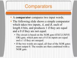
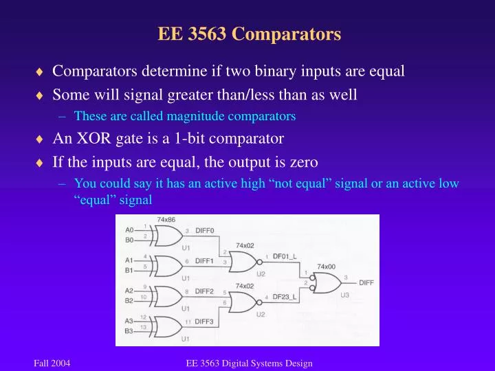
EE 3563 Comparators. Comparators determine if two binary inputs are equal Some will signal greater than/less than as well These are called magnitude comparators An XOR gate is a 1-bit comparator If the inputs are equal, the output is zero

E N D
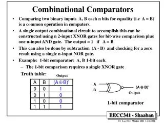
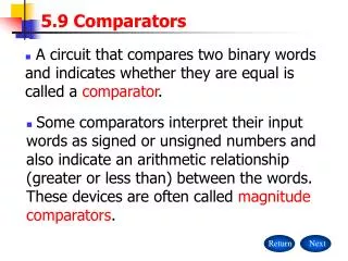
EE 3563 Comparators • Comparators determine if two binary inputs are equal • Some will signal greater than/less than as well • These are called magnitude comparators • An XOR gate is a 1-bit comparator • If the inputs are equal, the output is zero • You could say it has an active high “not equal” signal or an active low “equal” signal EE 3563 Digital Systems Design
EE 3563 Comparators • Comparators can be cascaded as well • The “diff” signal is propagated to the next comparator • This is similar to the ripple carry adder that we will examine shortly • The 74x85 is an MSI 4-bit comparator that has three outputs: • greater than, less than, equal • The 74x682 is an 8-bit comparator that has two outputs: • greater than, equal • These outputs could be used to determine less than, less than or equal, and greater than or equal What would you do to determine less than? EE 3563 Digital Systems Design
EE3563 Adders, Subtractors, ALUs • An adder – well, you all know what an adder is! • The adders work well for two’s complement and unsigned binary numbers • Refresher: 8-bit binary • 152 – 100110002 – unsigned • If you want to represent 152 as a signed number, then you need at least 9 bits! • The above binary number could also be considered a two’s complement signed number (-104) • The binary adders/subtractors do NOT work with sign-magnitude representation • Certainly, circuitry could be developed to do that, but it would have to handle the “negative 0” situation EE 3563 Digital Systems Design
EE3563 Adders, Subtractors, ALUs • A half adder adds two, 1-bit operands producing a 2-bit sum • The low order bit of the sum is called the half sum • The high order bit is called the carry out • add: X=1 + Y=1 • Half Sum: X xor Y = X*Y’ + X’*Y • Carry Out: X*Y • In order to add larger numbers, need a “Carry In” also • This is called a Full Adder 1 + 1 10 EE 3563 Digital Systems Design
EE3563 Full Adders • Sum = X xor Y xor CIN == X*Y’*CIN’ + X’*Y*CIN’ + X’*Y’*CIN + X*Y*CIN • COUT = X*Y + X*CIN + Y*CIN EE 3563 Digital Systems Design
EE3563 Full Adders • A Ripple Adder is simply a cascaded set of full adders • Each Carry Out feeds into the succeeding Carry In • The LSB Carry In is cleared • The ripple adder is slow since the carry must propagate through all the stages, i.e. a correct result will not be guaranteed to appear until that carry has propagated EE 3563 Digital Systems Design
EE3563 Subtractors • The full subtractor is very similar to the adder • The Carry In/Out is called the Borrow In/Out • The result is called the “difference” • The LSB Borrow In is set to one • D = X xor Y xor BIN • BOUT = X’*Y + X’*BIN + Y*BIN • Basically, we can subtract by adding the two’s complement of the subtrahend • in X-Y, X is the minuend, and Y is the subtrahend • The two’s complement of Y is Y’ + 1, hence the BIN is set to 1, and the inputs for Y are inverted • Which common type of gate allows us to control the inversion? EE 3563 Digital Systems Design
EE3563 Subtractors • The 8-bit adder/subtractor I did for VLSI used this technique • In order to add, should the Add/Subtract pin be high or low? • Note that the initial CIN should be 1 for subtraction, and 0 for addition – can we use the Add/Subtract input for this? EE 3563 Digital Systems Design
EE3563 Carry Lookahead Adder • The carry lookahead adder was developed to overcome the shortcomings of the ripple adder • Basically, all the carry bits are calculated in parallel with the sum bits • There is a “generate” signal which means that a carry out is produced at a particular stage independent of the previous inputs • In other words, ignore any Carry In signal • Both inputs at this stage must be 1 • There is a “propagate” signal which means that a carry out is produced when the Carry In is 1 • Either or both inputs are 1 and the Carry In is 1 • gi = Xi * Yi , pi = Xi + Yi • “i” is the stage EE 3563 Digital Systems Design
EE3563 Carry Lookahead Adder • The Carry Out of a stage can be written in terms of the generate and propagate signals: • ci+1 = gi + pi * ci • Applying this concept recursively, we can develop a three-level circuit to produce the carry signal at each stage • One level is for the generate and propagate signals • The other two levels are for the sum of products equations • The equations for the first four stages can be found on p.435 EE 3563 Digital Systems Design
EE3563 MSI Adders • The 74x283 is a 4-bit binary adder that uses the carry lookahead technique • The 74x83 is identical except for non-standard pinout • The half sum can be produced more cheaply from the generate and propagate signals, so this eliminates the need for XOR gates • The 74x283 adder can be cascaded to form an adder that can handle more bits EE 3563 Digital Systems Design
EE3563 MSI Arithmetic Logic Units (ALU) • The ALU is the heart of a microprocessor • It performs a variety of mathematical and logic functions • ADD, SUB, AND, OR, XOR, and current CPUs do MUL, DIV • All of the above functions can be performed using combinational logic • Other functions will be examined when we reach chapter 7 • The 74x181 4-bit ALU has a series of built-in functions EE 3563 Digital Systems Design
EE3563 MSI Arithmetic Logic Units (ALU) EE 3563 Digital Systems Design