Download
1 / 38

E N D
Dimensioning Dimensioning
Dimensioning The Ames Lettering Guide is a transparent plastic device composed of a frame holding a disc containing columns of holes. The vertical distances between the holes may be adjusted quickly to the desired spacing for guide lines or section lines by simply turning the disk to one of the settings indicated at the bottom of the disk. The numbers at the bottom of the disc indicate heights of letters in thirty-seconds of an inch. Thus for the Number 4 setting, the lettering height would be 4/32” or 1/8”.
Dimensioning The center column of holes (evenly spaced holes) is used primarily to draw guide lines for numerals, fractions, and general lettering. The height of whole numbers and general lettering will be two units and the height of fractions will be four units. Since the spaces are equal, these holes can also be used to draw equally spaced section lines. The sides of the guide are used to draw vertical or inclined guide lines.
Dimensioning Overview: Graphical entities on engineering drawings describe shape and position. Dimensions and notes describe size and necessary manufacturing processes if the engineering drawing is to be a complete instruction for the shop technician. Dimensions describe the size and location of features of an object. The correct placement of dimensions is strictly prescribed by an extensive list of drawing conventions.
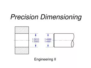
Dimensioning Size Description In addition to a complete shape description of an object, a drawing of the design must also give a complete size description, that is, it must be dimensioned. A drawing submitted to production should show the object in its completed condition (shape description) and should contain all necessary information to bring it to that final state. Only those dimensions needed to produce and inspect the part against the design specifications should be given, not the dimensions use to make the drawing.
Dimensioning • Learning to Dimension • The student must learn the technique of dimensioning: the character of the lines, the spacing of dimensions, the making of arrowheads, and so forth. • The student must learn the rules of placement of dimensions of the drawing. • The student should learn the choice of dimensions.
Dimensioning Lines used in dimensioning: Dimension line: A dimension line is a thin, dark line terminated by arrowheads and indicates the extent of the dimension. Extension line: An extension line is a thin, dark line that extends from a point on the drawing to which a dimension refers.
Dimensioning Spacing of dimension lines should be uniform throughout the drawing. The dimension line nearest the object should be spaced at least 3/8” away from the object. All other dimension lines should be spaced at least 1/4” apart. A 1/16” gap is left where the extension line would join the object outline and extends 1/8” past the outermost dimension line.
Dimensioning Center Line: A center line is a thin, dark line composed of alternate long and short dashes and is used to represent axes of symmetry and to denote centers. Center lines are commonly used as extension lines. When a center line crosses over an object line, it crosses the object line without a gap.
Dimensioning Arrowheads: Arrowheads indicate the extend of dimensions. Arrowheads are drawn freehand. The length of an arrowhead should be equal to the height of the lettering and the length and width should be in a ratio of 3:1
Dimensioning Placement of dimension and extension lines: The correct placement of dimension lines and extension lines are shown in figure (a). The shorter dimensions are placed nearest the object. Dimension lines should never cross an extension line (figure b). It is acceptable to cross extension lines with other extension lines but the extension lines should never be shortened (figure c). A dimension line should never coincide with or form a continuation of any other line of the drawing (figure d).
Dimensioning Dimensions should be lined up and grouped together as much as possible.
Dimensioning When extension lines and center lines cross visible object lines gaps should not be left in the lines.
Dimensioning Leaders: A leader is a thin, dark, solid line that leads from a note or dimension and terminates in an arrowhead. Arrowheads should always terminate on a line or edge of a hole. A leader to a circle should be radial and appear to pass through the center. Leaders should cross as few lines a possible and should never cross each other.
Dimensioning Dimension Figures: In a group of parallel dimension lines, the numerals should be staggered (figure a) and not stacked up one above the other (figure b).
Dimensioning Direction of dimension figures: There are two systems of reading direction for dimension figures, the unidirectional system and the aligned system. Unidirectional system: the dimension figures are lettered horizontally on the sheet and are read from the bottom of the drawing (figure a) Aligned system: the dimension figures are aligned with the dimension lines and are read from the bottom of the drawing or the right side (figure b).
Dimensioning Dimensioning Angles: Angles are dimensioned by giving the angle in degrees and a linear dimension (figure a) or by dimensioning the two legs of a right triangle (figure b). In all cases whether in the unidirectional system or in the aligned system the dimension figures for angles are lettered horizontally (figures c, d, e, f).
Dimensioning Dimensioning Arcs: A circular arc is always dimensioned in the view in which its true shape is shown.
Dimensioning Contour Dimensioning: Dimensions should be given where the shapes show true size and true shape.
Dimensioning Dimensioning Prisms: The height and width dimension of a prism should be given in the front view and the depth dimension given in the top or right-side view. Horizontal and vertical dimensions should be kept in line.
Dimensioning Dimensioning Cylinders: The general method of dimensioning a cylinder is to give its length and diameter in the rectangular view.
Dimensioning Dimensioning Cylinders: A leader can be used to dimension the circular view.
Dimensioning Dimensioning holes: Holes are usually specified by standard notes and a leader line.
Dimensioning The diameter symbol () should be given before all diameter dimensions.
Dimensioning Dimensioning Holes: Holes are dimensioned using leader lines pointing to the hole and shown where the hole appears circular. Dimensions and notes should always be lettered horizontally of the drawing.
Dimensioning Locating Holes: Location dimensions for holes are given in the circular view of the holes where the holes appear true size and true shape.
Dimensioning Locating holes about a center: Holes equally spaced about a common center may be dimensioned by giving the diameter of the circle of centers (figure a). Unequally spaced holes are located by dimensioning the bold circle diameter plus angular measurements (figure b). Where greater accuracy is required, coordinate dimensions should be given (figure c).
Dimensioning Dimensioning rounded-end shapes: The method for dimensioning rounded-end shapes depends of the degree of accuracy required. Shown are examples of dimensioning rounded-end shapes.
Dimensioning Superfluous Dimensions: All necessary dimensions must be shown on a drawing. Avoid giving unnecessary or superfluous dimensions. Dimensions should not be repeated or the same dimension given in two different ways.
Dimensioning Notes: Local notes that apply to specific operations only are connected by a leader to the point at which such operations are performed. The leader should be attached to the front of the first word of a note or after the last word. Notes are always lettered horizontally on the drawing sheet.
Dimensioning Notes:
Dimensioning Dimensioning Chamfers: A chamfer is a beveled or sloping edge. A chamfer is dimensioned by giving the length of the offset and the angle (figure a). A chamfer can also be dimensioning using a leader line (figure b).
Dimensioning Dimensioning Keyways:
Dimensioning Dimensioning knurls: A knurl is a roughened surface to provide a better handgrip or to be used for a press fit between two parts. A knurl is dimensioned by specifying the pitch of the knurl, the type of knurling, and the length of the knurled area.
Dimensioning • Mr. Ference’s rules for dimensioning: • Always use guidelines for all dimension numbers and text. • Spacing for all dimension lines should be uniform and consistent. • Never cross a dimension line. • Place dimensions where the feature shows both true size and true shape.