Download

1 / 81
880 likes | 1.58k Views
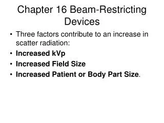
Chapter 16 Beam-Restricting Devices. Three factors contribute to an increase in scatter radiation: Increased kVp Increased Field Size Increased Patient or Body Part Size . X-ray Interactions. a – some interact with the patient and are scattered away from the patient. b – some are absorbed

E N D
Chapter 16 Beam-Restricting Devices • Three factors contribute to an increase in scatter radiation: • Increased kVp • Increased Field Size • Increased Patient or Body Part Size.
X-ray Interactions • a – some interact with the patient and are scattered away from the patient. • b – some are absorbed • c - some pass through without interaction • d – some are scattered in the patient • c & d are image forming x-rays.
Percent Interaction of Scatter and Percent Transmission through 10 cm of Tissue
Beam-Restricting Devices • There are two principal means to reduce scatter radiation: • Beam Restricting Devices limit the field size to reduce scatter and primary radiation. • Grids to absorb scatter before it reached the image receptor.
Beam-Restricting Devices • There are three principal types of beam restricting devices: • Aperture Diaphragm • Cones & Cylinders • Collimators
Production of Scatter Radiation • Two kinds of x-rays are responsible for the optical density, or degree of blackening on a radiograph. • Those that pass through the patient without interacting called remnant ray. • Those that are scattered through Compton interaction.
Kilovolt Peak • As x-ray energy increases, the relativenumber of x-rays that undergo Compton Scattering increases. • The absolute number of the Compton interactions decrease with increasing energies but the number of photoelectric interactions decreases more rapidly.
Field size • The size of the field or area being irradiated has a significant impact on scatter radiation. • Field size is computed in square inches or square cm
Field size • Scatter radiation increases as the field size increases. • The relative intensity of the scatter varies more when the field size is small than when the field is large.
Field size • When the field size is reduced, the resulting reduction in scatter will reduce the density on the image. • The mAs must be increased to maintain density. • The reduced scatter will improve contrast resolution resulting in improved image quality.
Field size • To change from a 14” x 17” to a 10” x 12” increase mAs 25%. • To change from a 14” x 17” to a 8” x 10” increase mAs 40%.
Patient or Part Thickness • More scatter results from imaging thick body parts compared to thin body parts. • There will be more scatter for a lumbar spine film compared to a cervical spine film. • As tissue thickness increases, more of the rays go through multiple scattering.
Tissue Thickness • The relative intensity of scatter radiation increases with increasing thickness of the anatomy. • The amount of primary radiation also increases to compound the scatter.
Patient thickness • Normally body thickness is out of our control but we can change the method of imaging to improve image quality. • With obese patients, tissue thickness is reduced when taking the film recumbent due to compression. • Be sure and measure the patient recumbent.
Types of Beam Restricting Devices • There are three types of beam restricting devices. • Diaphragms • Cones • Collimators
Types of Beam Restricting Devices • Large field sizes result in more scatter radiation that reduces image contrast.
Aperture Diaphragm • Aperture diaphragms are basically lead or lead lines metal devices placed in the beam to restrict the x-rays emitted from the tube.
Aperture Diaphragm • Apertures are the simplest form of collimation. • In this case, the aperture is used to reduce exposure to the breast tissue.
Aperture Diaphragm • The width or size of the aperture is fixed and can not be adjusted. • The operator must be careful when placing the aperture in the beam.
Cones and Cylinders • Cones and cylinders are modifications to the aperture. • Cones are typically used in dental radiography.
Cones and Cylinders • Most cone produce a round image on a rectangular film. • Cones are very effective at reducing scatter. • Hard to center.
Variable Aperture Collimator • Proper collimation of the x-ray beam has the primary effect of reducing patient dose by restricting the volume of tissue irradiated.
Variable Aperture Collimator • Proper collimation also reduces scatter radiation that improves contrast.
Light Localizing Collimator • The light localizing variable aperture collimator is the most common beam restricting device in diagnostic radiography.
Collimator • Not all of the x-rays are emitted precisely from the focal spot. • These rays are called off-focus radiation and they increase image blur.
Collimator • First stage shutters protrude into the tube housing to control the off-focus radiation. • Adjustable second stage shutter pairs are used to restrict the beam.
Collimator • Light localization is accomplished by a small projector lamp and mirror to project the setting of the shutters on the patient.
Collimator • The light field and x-ray beam should match to avoid collimator cut-off. • A scale on the collimator is used to match the beam to the film size at fixed SID’s.
Collimator • Many newer collimators a bright slit of light is provided to properly center the beam and the film. • Units manufactured between 1974 and 1994 has motorized shutters.
Collimator • A sensor in the Bucky and the motor were used to automatically collimate the image to film size. This was called a positive-beam limiting (PBL) device. • Required by the FDA.
Collimator • Requirement was repealed in 1994. • If the beam is not centered to the film, collimator cut-off will occur on the top or bottom of the image.
Collimator • If the tube is not centered to the Bucky or the film is not pushed into the Bucky, side to side collimator cut-off will occur.
Collimation Rules • California required three borders of collimation to be seen on the film. • Collimation must be slightly less than film size or to the area of clinical interest, whichever is smaller. • ANY exposure beyond the film is unnecessary patient exposure.
Chapter 17 The Grid • So far we have discussed how kVp, patient size and collimation impact scatter radiation. • As the part size and kVp increase, scatter is increased. • Using low kVp reduces less scatter but increases patient dose.
The Grid • Collimation reduces scatter radiation but that alone is not sufficient for larger body parts. • With thick and dense body parts, almost all of the remnant rays are scattered many times. This results in reduced image contrast.
Grids • An extremely effective means for reducing scatter radiation that reaches the film is called a grid.
Grid • In 1913, Gustave Bucky demonstrated that strips of lead interspaced with radiolucent material is an effective means to reduce scatter radiation reaching the film. • Only rays that travel in a relatively straight line from the source are allowed to reach the film. • The others are absorbed by the lead.
Grid • Primary beam x-rays striking the interspace material are allowed to pass to the film. • Secondary radiation that strike the interspace material may or may not pass on to the film. • High quality grids will attenuate 80% to 90% of the scatter radiation.
Grid Construction • There are three important aspects of grid construction; • Grid Ratio • Grid Frequency • Grid material
Grid Ratio • There are three important dimensions on a grid. • Width of the grid strip (T) • Width of the interspace material (D) • Height of the grid (h)
Grid Ratio • High ratio grids are more effective in cleaning up scatter radiation because the angle of scatter allowed by the high ratio is less than permitted to pass by low ratio grids.
Grid Ratio • High ratio grids are more expensive and harder to produce. • The width of the interspace material is reduced while increasing the height of the grid material in order to increase the ratio. • Ratios range from 5:1 to 16:1 • High ratio grids increase patient dose.
Grid Ratio • 8:1 and 10:1 grids are the most popular ratios in general radiography. • 8:1 grids are commonly found on single phase machines. • 10:1 are often found on high frequency machines.
Grid Frequency • The number of grid lines per inch or centimeter is called the Grid Frequency. • Grids with high frequency show less distinct grid lines on the film. • The higher the frequency of the grid, the thinner its strips of interspace material and the higher the ratio.
Grid Frequency • The use of high frequency grids requires high radiographic technique and results in higher patient radiation dose. • Grid frequency range from 25 to 45 lines per centimeter or 60 to 200 lines per inch. • The advantage of high frequency grids is there are no objectionable grid lines on the image.
Grid Frequency • High frequency grids allow the removal of a mechanism to move the grid during the exposure. This mechanism make the grid a Potter-Bucky Diaphragm instead of a grid holder.
Grid Material • The most common grid material is lead because of its cost and ease of forming the strips. • The interspace material is used to maintain a precise separation of the lead strips. • Plastic fiber or aluminum is used as the interspace material.
Grid Material • Plastic fiber is more common as it does not attenuate the beam as it passes through the interspace. • Aluminum interspace requires an increase in the technical factors by as much as 20%. • Plastic fiber can absorb moisture resulting in warping of the grid.
Grid Material • Aluminum is also easier to form and manufacture with high tolerances. • Aluminum is used as the cover for the grid to protect it from damage and moisture.