Download
1 / 104
1.07k likes | 1.64k Views
Ch. 3 Wireless Radio Technology. Cisco Fundamentals of Wireless LANs version 1.1 Rick Graziani Cabrillo College Spring 2005. Note. Some of this information should be a review from CCNA 1: Sine waves, modulation, etc. Please review your CCNA materials if needed.

E N D
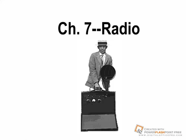
Ch. 3 Wireless Radio Technology Cisco Fundamentals of Wireless LANs version 1.1 Rick Graziani Cabrillo College Spring 2005
Note • Some of this information should be a review from CCNA 1: • Sine waves, modulation, etc. • Please review your CCNA materials if needed. • This module contains several mathematical formulas. • Examples will be included, but we will not discuss them in any detail, nor will you be responsible for them on any exam. Rick Graziani graziani@cabrillo.edu
Acknowledgements • Thanks Jack Unger and his book Deploying License-Free Wireless Wide-Area Networks • Published by Cisco Press • ISBN: 1587050692 • Published: Feb 26, 2003 Rick Graziani graziani@cabrillo.edu
Overview of Waves • Wave is a “disturbance or variation” that travels through a medium. • The medium through which the wave travels may experience some local oscillations as the wave passes, but the particles in the medium do not travel with the wave. • Just like none of the individual people in the stadium are carried around when they do the wave, they all remain at their seats. Rick Graziani graziani@cabrillo.edu
Waves • Waves are one way in which energy can move from one place to another. • The waves that you see at the beach are the result of the kinetic energy of water particles passing through the water. • Other types of energy (such as light, heat, and radio waves) can travel in this way as well. • The distance between 2 peaks (or 2 troughs) is called a wavelength • The deepest part of a trough or the highest part of a peak is called the amplitude • The frequency is the number of wavelengths that pass by in 1 second www.ewart.org.uk Rick Graziani graziani@cabrillo.edu
Longitudinal Waves • Longitudinal sound waves in the air behave in much the same way. • As the sound wave passes through, the particles in the air oscillate back and forth from their equilibrium positions but it is the disturbance that travels, not the individual particles in the medium. • Rick talks in a loud voice and he causes the air near his mouth to compress. • A compression wave then passes through the air to the ears of the people around him. • A longitudinal sound wave has to travel through something - it cannot pass through a vacuum because there aren't any particles to compress together. • It has a wavelength; a frequency and an amplitude. Curriculum 3.1.1 www.ewart.org.uk Rick Graziani graziani@cabrillo.edu
Transverse Waves • Transverse waves on a string are another example. • The string is displaced up and down, as the wave travels from left to right, but the string itself does not experience any net motion. • A light wave is a transverse wave. • If you look at the waves on the sea they seem to move in one direction .... towards you. • However, the particles that make up the wave only move up and down. • Look at the animation, on the right, although the wave seems to be moving from left to right the blue particle is only moving up and down. Rick Graziani graziani@cabrillo.edu
Sine waves • The sine wave is unique in that it represents energy entirely concentrated at a single frequency. • An ideal wireless signal has a sine waveform • With a frequency usually measured in cycles per second or Hertz (Hz). • A million cycles per second is represented by megahertz (MHz). • A billion cycles per second represented by gigahertz (GHz). Rick Graziani graziani@cabrillo.edu
Sine waves • Amplitude – The distance from zero to the maximum value of each alternation is called the amplitude. • The amplitude of the positive alternation and the amplitude of the negative alternation are the same. • Period – The time it takes for a sine wave to complete one cycle is defined as the period of the waveform. • The distance traveled by the sine wave during this period is referred to as its wavelength. • Wavelength – Indicated by the Greek lambda symbol λ. • It is the distance between one value to the same value on the next cycle. • Frequency – The number of repetitions or cycles per unit time is the frequency, typically expressed in cycles per second, or Hertz (Hz). Curriculum 3.1.2 Rick Graziani graziani@cabrillo.edu
Sine waves • One full period or cycle of a sine wave is said to cover 360 degrees (360°). • It is possible for one sine wave to lead or lag another sine wave by any number of degrees, except zero or 360. • When two sine waves differ by exactly zero° or 360°, the two waves are said to be in phase. • Two sine waves that differ in phase by any other value are out of phase, with respect to each other. Go to interactive activity 3.1.2 Amplitude, Frequency, and Phase 180° Phase Shift Rick Graziani graziani@cabrillo.edu
Analog to digital conversion • Analog wave amplitudes are sampled (measuring the analog wave) at specific instances in time. • More samples means more bits. • Sampling rate more than twice the frequency is not efficient. • Each sample is assigned a discrete value. • Each discrete value is converted to a stream of bits. Go to interactive activity 3.1.3 Rick Graziani graziani@cabrillo.edu
Fourier synthesis Go to interactive activity 3.3.3 Whatis.com • Jean Baptiste Fourieris responsible for one of the great mathematical discoveries. • When two EM waves occupy the same space, their effects combine to form a new wave of a different shape. • It works by combining a sine wave signal and sine-wave or cosine-wave harmonics (signals at multiples of the lowest, or fundamental, frequency) in certain proportions. • A square wave, or a square pulse, can be built by using the right combination of sine waves. Rick Graziani graziani@cabrillo.edu
Bandwidth • Analog bandwidth • Analog bandwidth can refer to the range of frequencies, or cycles per second, which is measured in Hz. • There is a direct correlation between the analog bandwidth of any medium and the data rate in bits per second that the medium can support. • Digital bandwidth • Digital bandwidth is a measure of how much information can flow from one place to another, in a given amount of time. • Digital bandwidth is measured in bits per second. • When dealing with data communications, the term bandwidth most often signifies digital bandwidth. Rick Graziani graziani@cabrillo.edu
Basics of EM waves • EM waves exhibit the following properties: • reflection or bouncing • refraction or bending • diffraction or spreading around obstacles • scattering or being redirected by particles • This will be discussed in greater detail later in this module. • Also, the frequency and the wavelength of an EM wave are inversely proportionally to one another. Rick Graziani graziani@cabrillo.edu
Basics of EM waves • There are a number of properties that apply to all EM waves, including: • Direction • Frequency • Wavelength • Power • Polarization • Phase. Rick Graziani graziani@cabrillo.edu
Basics of EM waves • EM (Electromagnetic)spectrum a set of all types of radiation when discussed as a group. • Radiation is energy that travels in waves and spreads out over distance. • The visible light that comes from a lamp in a house and radio waves that come from a radio station are two types of electromagnetic waves. • Other examples are microwaves, infrared light, ultraviolet light, X-rays, and gamma rays. Rick Graziani graziani@cabrillo.edu
Basics of EM waves • All EM waves travel at the speed of light in a vacuum and have a characteristic wavelength (λ) and frequency (f), which can be determined by using the following equation: • c = λ x f, where c = the speed of light (3 x 10⁸ m/s) • Wavelength x Frequency = Speed of light • Speed of light = 180,000 miles/sec or 300,000 kilometers/sec or 300,000,000 meters/sec Interactive activity 3.3.1 Rick Graziani graziani@cabrillo.edu
EM Spectrum Chart Interactive activity 3.3.2 • One of the most important diagrams in both science and engineering is the chart of the EM spectrum . • The typical EM spectrum diagram summarizes the ranges of frequencies, or bands that are important to understanding many things in nature and technology. • EM waves can be classified according to their frequency in Hz or their wavelength in meters. • The most important range for this course is the RF (Radio Frequency) spectrum. Rick Graziani graziani@cabrillo.edu
EM Spectrum Chart • The RF spectrum includes several frequency bands including: • Microwave • Ultra High Frequencies (UHF) • Very High Frequencies (VHF) • This is also where WLANs operate. • The RF spectrum ranges from 9 kHz to 300 GHz. • Consists of two major sections of the EM spectrum: (RF Spectrum) • Radio Waves • Microwaves. • The RF frequencies, which cover a significant portion of the EM radiation spectrum, are used heavily for communications. • Most of the RF ranges are licensed, though a few key ranges are unlicensed. Rick Graziani graziani@cabrillo.edu
EM Spectrum Chart Nasa.gov Rick Graziani graziani@cabrillo.edu
Nasa.gov Rick Graziani graziani@cabrillo.edu
www.britishlibrary.net Rick Graziani graziani@cabrillo.edu
Licensed Frequencies • Frequency bands have a limited number of useable different frequencies, or communications channels. • The electromagnetic spectrum is a finite resource. • One way to allocate this limited, shared resource is to have international and national institutions that set standards and laws as to how the spectrum can be used. • In the US, it is the FCC that regulates spectrum use. • In Europe, the European Telecommunications Standards Institute (ETSI) regulates the spectrum usage. • Frequency bands that require a license to operate within are called the licensed spectrum. • Examples include amplitude modulation (AM) and frequency modulation (FM) radio, ham or short wave radio, cell phones, broadcast television, aviation bands, and many others. • In order to operate a device in a licensed band, the user must first apply for and be granted the appropriate license. Rick Graziani graziani@cabrillo.edu
ISM (Industrial, Scientific, and Medical) & U-NII (Unlicensed National Information Infrastructure) • Some areas of the spectrum have been left unlicensed. • This is favorable for certain applications, such as WLANs. • An important area of the unlicensed spectrum is known as the industrial, scientific, and medical (ISM) bands and the U-NII (Unlicensed National Information Infrastructure) • ISM – 802.11b, 802.11g • U-NII – 802.11a • These bands are unlicensed in most countries of the world. • The following are some examples of the regulated items that are related to WLANs: • The FCC has defined eleven 802.11b DSSS channels and their corresponding center frequencies. ETSI has defined 13. • The FCC requires that all antennas that are sold by a spread spectrum vendor be certified with the radio with which it is sold. • Unlicensed bands are generally license-free, provided that devices are low power. • After all, you don’t need to license your microwave oven or portable phone. Rick Graziani graziani@cabrillo.edu
Signals See Figure 2 in 3.4.1 • One of the most important facts of the information age is that data can be represented electrically by voltage patterns on wires and in electronic devices. • The data in electronic devices, which is represented by voltage patterns, can be converted to radio waves and radio waves can be converted to voltage patterns. • Since voltages are much easier to measure than directly measuring the radio waves, an understanding of voltage patterns can be very helpful in the study of WLANs, which are made up of electronic devices. Rick Graziani graziani@cabrillo.edu
Time Domain Analysis • The study of how signals vary with time is called time domain analysis. • To understand frequency-domain analysis as it relates to WLANs, it is helpful to first examine a more familiar radio system, namely commercial broadcast FM radio. • The different stations each have a different center or carrier frequency so that they do not transmit on the same frequencies. • The strength of the signal at the FM radio receiver may be weak or strong. • These same factors exist in a WLAN. For example, to gain the most benefit from multiple APs in the same location, it is important that they do not overlap in frequency. Rick Graziani graziani@cabrillo.edu
Digital Signals in Time Interactive activity 3.4.1 • Imagine several sine waves all added together at one time. The resulting wave is more complex than a pure sine wave. There are several tones and the graph of these tones will show several individual lines, each corresponding to the frequency of one tone. • The pattern of voltage changes versus time is called a square wave. Figure above illustrates a very simple example in which there are only two voltage levels, which will be interpreted as either a one or a zero. • Remember the Fourier synthesis and that a square wave can be built by using the right combination of sine waves. Rick Graziani graziani@cabrillo.edu
Modulation Techniques – Carrier frequencyInteractive Activity 3.5.2 • A carrier frequency is an electronic wave that is combined with the information signal and carries it across the communications channel. • An FM radio station typically has call letters associated with it, such as KPBS or 101.1 MHz. For WLANs, the carrier frequency is 2.4 GHz or 5 GHz. • Using carrier frequencies in WLANs has an added complexity, in that the carrier frequency is changed by frequency hopping or direct sequence chipping, to make the signal more immune to interference and noise. • The process of recovering the information from the carrier waves is called demodulation.. Rick Graziani graziani@cabrillo.edu
Interactive activity 3.5.2 • There are three aspects of the basic carrier wave that can be modulated: Amplitude, Frequency Phase or angle. • The three corresponding techniques are as follows: • Amplitude modulation (AM) • Frequency modulation (FM) • Phase modulation (PM) • Most communication systems use some form or combination of these three basic modulation techniques. • Amplitude shift keying (ASK) - Turning the amplitude all the way off • Frequency shift keying (FSK) - Hopping to an extreme frequency • Phase shift keying (PSK) - Shifting the phase 180 degrees Rick Graziani graziani@cabrillo.edu
http://www.sfu.ca/sonic-studio/handbook/Fourier_Synthesis.htmlhttp://www.sfu.ca/sonic-studio/handbook/Fourier_Synthesis.html Sound Example:Addition of the first 14 sine wave harmonics resulting in the successive approximation of a sawtooth wave. Rick Graziani graziani@cabrillo.edu
Wireless Propagation • There are several important simplifications which can be made. • In a vacuum, 2.4 GHz microwaves travel at the speed of light. • Once started, these microwaves will continue in the direction they were emitted forever, unless they interact with some form of matter. • In the atmosphere, the microwaves are traveling in air, not in a vacuum. • This does not significantly change their speed. • Similar to light, when RF travels through transparent matter, some of the waves are altered. • 2.4 & 5 GHz microwaves also change, as they travel through matter. • Amount of alteration depends heavily on the frequency of the waves and the matter. • Wireless propagation is the total of everything that happens to a wireless signal as the signal travels from Point A to Point B. • The study of how EM waves travel and interact with matter can become extremely complex. Rick Graziani graziani@cabrillo.edu
Wireless Propagation Mental picture • Wave is not a spot or a line, but a moving wave. • Like dropping a rock into a pond. • Wireless waves spread out from the antenna. • Wireless waves pass through air, space, people, objects,… Rick Graziani graziani@cabrillo.edu
Attenuation • Attenuation is the loss in amplitude that occurs whenever a signal travels through wire, free space, or an obstruction. • At times, after colliding with an object the signal strength remaining is too small to make a reliable wireless link. Same wavelength (frequency), less amplitude. Rick Graziani graziani@cabrillo.edu
Attenuation and Obstructions • Longer the wavelength (lower frequency) of the wireless signal, the less the signal is attenuated. • Shorter the wavelength (higher frequency) of the wireless signal, the more the signal it is attenuated. Same wavelength (frequency), less amplitude. Rick Graziani graziani@cabrillo.edu
Attenuation and Obstructions • The wavelength for the AM (810 kHz) channel is 1,214 feet • The larger the wavelength of the signal relative to the size of the obstruction, the less the signal is attenuated. • The shorter the wavelength of the signal relative to the size of the obstruction, the more the signal is attenuated. Rick Graziani graziani@cabrillo.edu
Reflected Waves Interactive Activity 3.7.3 • When a wireless signal encounters an obstruction, normally two things happen: • Attenuation – The shorter the wavelength of the signal relative to the size of the obstruction, the more the signal is attenuated. • Reflection – The shorter the wavelength of the signal relative to the size of the obstruction, the more likely it is that some of the signal will be reflected off the obstruction. Rick Graziani graziani@cabrillo.edu
Microwave Reflections • Microwave signals: • Frequencies between 1 GHz – 30 GHz (this can vary among experts). • Wavelength between 12 inches down to less than 1 inch. • Microwave signals reflect off objects that are larger than their wavelength, such as buildings, cars, flat stretches of ground, and bodes of water. • Each time the signal is reflected, the amplitude is reduced. Rick Graziani graziani@cabrillo.edu
Reflection • Reflection is the light bouncing back in the general direction from which it came. • Consider a smooth metallic surface as an interface. • As waves hit this surface, much of their energy will be bounced or reflected. • Think of common experiences, such as looking at a mirror or watching sunlight reflect off a metallic surface or water. • When waves travel from one medium to another, a certain percentage of the light is reflected. • This is called a Fresnel reflection (Fresnel coming later). Rick Graziani graziani@cabrillo.edu
Reflection • Radio waves can bounce off of different layers of the atmosphere. • The reflecting properties of the area where the WLAN is to be installed are extremely important and can determine whether a WLAN works or fails. • Furthermore, the connectors at both ends of the transmission line going to the antenna should be properly designed and installed, so that no reflection of radio waves takes place. Rick Graziani graziani@cabrillo.edu
Multipath Reflection • Advantage: Can use reflection to go around obstruction. • Disadvantage: Multipath reflection – occurs when reflections cause more than one copy of the same transmission to arrive at the receiver at slightly different times. Usually caused by poor signal quality levels or high RF signal strength Multipath Reflection Interactive Activity 3.7.5 Rick Graziani graziani@cabrillo.edu
Diffraction • Diffraction of a wireless signal occurs when the signal is partially blocked or obstructed by a large object in the signal’s path. • A diffracted signal is usually attenuated so much it is too weak to provide a reliable microwave connection. • Do not plan to use a diffracted signal, and always try to obtain an unobstructed path between microwave antennas. Diffracted Signal Rick Graziani graziani@cabrillo.edu
Refraction Sub-Refraction • Refraction (or bending) of signals is due to temperature, pressure, and water vapor content in the atmosphere. • When a ray of light traveling in one medium enters a second medium and is not perpendicular to the surface of this second medium, it bends • The refractivity gradient (k-factor) usually causes microwave signals to curve slightly downward toward the earth, making the radio horizon father away than the visual horizon. • This can increase the microwave path by about 15%, Interactive Activity 3.7.2 Refraction (straight line) Normal Refraction Earth Rick Graziani graziani@cabrillo.edu
Working with Wireless Power • Power can be: • Increased (gain) • Decreased (loss) • Power can be: • Relative (ex: twice as much power or ½ as much power) • Absolute (ex: 1 watt or 4 watts) • Both relative and absolute power are always referenced to initial power level: • Relative power level • Absolute power level • Wireless power levels become very small, very quickly after leaving the transmitting antenna. • Wireless power levels are done in decibel (dB), a unit that is used to measure electrical power. • A dB is one-tenth (1/10th) of a Bel, which is a unit of sound named after Alexander Graham Bell. Rick Graziani graziani@cabrillo.edu
Inverse square law • “Signal strength does not fade in a linear manner, but inversely as the square of the distance. • This means that if you are a particular distance from an access point and you move measure the signal level, and then move twice a far away, the signal level will decrease by a factor of four.” Twice the distance Point A Point B ¼ the power of Point A Rick Graziani graziani@cabrillo.edu
Inverse square law 10 20 30 40 50 100 • Double the distance of the wireless link, we receive only ¼ of the original power. • Triple the distance of the wireless link, we receive only 1/9 the original power. • Move 5 times the distance, signal decreases by 1/25. Point A 10 times the distance 1/100 the power of A 3 times the distance 1/9 the power of Point A 2 times the distance ¼ the power of Point A 5 times the distance 1/25 the power of Point A Rick Graziani graziani@cabrillo.edu
Watts • One definition of energy is the ability to do work. • There are many forms of energy, including: • electrical energy • chemical energy • thermal energy • gravitational potential energy • The metric unit for measuring energy is the Joule. • Energy can be thought of as an amount. • 1 Watt = I Joule of energy / one second • If one Joule of energy is transferred in one second, this is one watt (W) of power. Rick Graziani graziani@cabrillo.edu
Watts • The U.S. Federal Communications Commission allows a maximum of 4 watts of power to be emitted in point-to-multipoint WLAN transmissions in the unlicensed 2.4-GHz band. • In WLANs, power levels as low as one milliwatt (mW), or one one-thousandth (1/1000th) of a watt, can be used for a small area. • Typical WLAN NICS transmit at 100 mW. • Typical Access Points can transmit between 30 to 100 mW (plus the gain from the Antenna). Rick Graziani graziani@cabrillo.edu
Watts • Power levels on a single WLAN segment are rarely higher than 100 mW, enough to communicate for up to three-fourths of a kilometer or one-half of a mile under optimum conditions. • Access points generally have the ability to radiate from 30 to100 mW, depending on the manufacturer. • Outdoor building-to-building applications (bridges) are the only ones that use power levels over 100 mW. Rick Graziani graziani@cabrillo.edu
Decibels • The dB is measured on a base 10 logarithmic scale. • The base increases ten-fold for every ten dB measured. The decibel scale allows people to work more easily with large numbers. • A similar scale called the Richter Scale. • The Richter scale is logarithmic, that is an increase of 1 magnitude unit represents a factor of ten times in amplitude. • The seismic waves of a magnitude 6 earthquake are 10 times greater in amplitude than those of a magnitude 5 earthquake. • Each whole number increase in magnitude represents a tenfold increase in measured amplitude; as an estimate of energy. 10x 10x Rick Graziani graziani@cabrillo.edu