Download
1 / 38
440 likes | 1.52k Views
Introduction to Mechanical Ventilation. Spontaneous Breathing. Positive Pressure Breath. Goals of Mechanical Ventilation. Maintain ABG’s Optimize V/Q Decrease Myocardial Workload. Indications for Mechanical Ventilation. Apnea Acute Ventilatory Failure Ph 7.30 or <, with PaCO2 50 or >

E N D
Goals of Mechanical Ventilation • Maintain ABG’s • Optimize V/Q • Decrease Myocardial Workload
Indications for Mechanical Ventilation • Apnea • Acute Ventilatory Failure • Ph 7.30 or <, with PaCO2 50 or > • Clinical Signs • Impending Ventilatory Failure • Acute Respiratory Failure
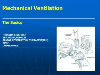
Two Ways to Achieve Continuous Mechanical Ventilation, ie CMV • Negative pressure • Positive pressure
Positive Pressure Flow Pattern Considerations Flow = Pressure divided by resistance
Positive Pressure Flow Patterns • Constant flow or Square Wave • Flow stays constant as resistance varies • Thus pressure and resistance vary directly
Positive Pressure Flow Patterns • Accelerating/decelerating or sine wave • Peak flow occurs at mid-inspiration • Mimics spontaneous breathing
Positive Pressure Flow Patterns • Constant Pressure or tapered flow • Flow (and hence tidal volume) vary with resistance
Flow Patterns Summary • Constant flow or square wave • Sine Wave • Constant Pressure or tapered wave
Cycling Cycling refers to how the ventilator ends the inspiratory phase of the breath
Cycling Mechanisms • Volume cycling – inspiration ends when a preset tidal volume is delivered • Pressure cycling – inspiration ends when a preset pressure is reached on the airway • Time cycling – inspiration ends when a preset inspiratory time has elapsed • Flow cycling – inspiration ends when a preset flow has been reached
Triggering The mechanism that starts the inspiratory phase
Trigger Mechanisms • Pressure triggered – a drop in airway pressure triggers the ventilator • Flow triggered – a constant (bias) flow of gas passes through the ventilator circuit. When the patient starts to inhale the ventilator detects the drop in bias flow and triggers • Types of triggered breaths: patient = assisted; ventilator = controlled, operator = manual
Hazards – Positive Pressure CMV • Increased mean intrathoracic pressure • Decreased venous return • Increased intracranial pressure • Pulmonary Volu/Barotrauma • Fluid retention • Gastric Ulcers • Muscle Atrophy & Patient Dependence • Mechanical Failure • Mismanagement • Contamination/Infection
Preventing Hazards • Maintain good I:E ratio • Make sure flow meets patient’s demand • Attention to patient and ventilator • FREQUENT HANDWASHING!
Other Modes • High Frequency Ventilation (HFV) • Pressure Control ( time cycling) • Pressure Support (flow cycling) • Airway Pressure Release Ventilation (APRV)
Peak Pressure • Pressure on manometer immediately at end of inspiratory phase • Represents pressure needed to overcome both elastic and airway resistance • Used to calculate dynamic compliance • Cdyn = VT/Peak pressure • PEAK PRESSURE WILL CHANGE WHEN EITHER ELASTIC OR AIRWAY RESISTANCE CHANGES!
Plateau Pressure • Pressure on manometer after inspiration has ended but before expiration has started • Represents pressure needed to overcome elastic resistance only • Used to calculate static compliance • Cstat = VT/plateau pressure • PLATEAU PRESSURE CHANGES ONLY WHEN ELASTIC RESISTANCE CHANGES
Clinical Analysis By Comparing Peak and Plateau Pressure Changes • Remember – a change in elastic resistance will affect both peak and plateau pressure • Remember – a change in airway resistance only affects the peak pressure • Compare the change in plateau pressures first, then compare the changes in peak pressure
Resistance and Pressure Vary Directly Resistance and Pressure Vary Inversely With Compliance
Initial Values Peak = 28 cmH2O Plateau = 23 cmH2O 2 Hours later -peak = 32 cmH2O -plateau = 27 cmH2O
Initial Values Peak = 31 cmH2O Plateau = 25 cmH2O 2 Hours Later Peak = 40 cmH2O Plateau = 25 cmH2O
Initial Values Peak = 49 cmH20 Plateau = 30 cmH2O 2 Hours Later Peak = 49 cmH2O Plateau = 26 cmH2O
Initial Values Peak = 36 cmH2O Plateau = 29 cmH2O 2 Hours Later Peak = 32 cmH2O Plateau = 29 cmH20
Initial Values Peak = 29 cmH2O Plateau = 22 cmH2O 2 Hours Later Peak = 41 cmH2O Plateau = 28 cmH2O
Initial Values Peak = 33 cmH2O Plateau = 21 cmH2O 2 Hours Later Peak = 34 cmH2O Plateau = 19 cmH2O
Now lets have some Fun with more math!