Download
1 / 23
230 likes | 440 Views
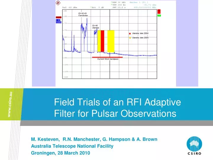
Field Trials of an RFI Adaptive Filter for Pulsar Observations. M. Kesteven, R.N. Manchester, G. Hampson & A. Brown Australia Telescope National Facility Groningen, 28 March 2010. Outline. Introduction Adaptive Filter details Results Conclusions. Introduction.

E N D
Field Trials of an RFI Adaptive Filter for Pulsar Observations M. Kesteven, R.N. Manchester, G. Hampson & A. Brown Australia Telescope National Facility Groningen, 28 March 2010
Outline • Introduction • Adaptive Filter details • Results • Conclusions RFI mitigation. Groningen, 2010
Introduction • The RFI mitigation work at the Parkes Observatory was given greater emphasis when one of the Parkes Pulsar observing bands became heavily polluted with RFI (digital TV). • The prospects were favourable: • The levels were substantial, but not so large as to overload the system. • Some of the critical hardware needed was already in place. • A new digital backend with reserve capacity came on-line. • An adaptive filter works well with pulsar observing. RFI mitigation. Groningen, 2010
Introduction (II) • The Parkes Observatory recently commissioned a new pulsar processing machine. This a digital polyphase filterbank that is capable of 8-bit sampling at a rate of 2GHz for an observational bandwidth of up to 1GHz. It supports a range of configurations including an online-folding mode with up to 2048 pulse phase and radio frequency bins. • For observations in the 50cm (~700 MHz) band there is spare capacity which could readily be deployed for RFI mitigation. • This takes the form of an adaptive filter in conjunction with a reference antenna directed towards a TV tower, the source of RFI for the receiver’s band. RFI mitigation. Groningen, 2010
The basic narrow-band adaptive filter RFI mitigation. Groningen, 2010
Filter details = residual RFI / unfiltered RFI RFI mitigation. Groningen, 2010
The broad band filter, as implemented RFI mitigation. Groningen, 2010
RFI Mitigation On! PDFB3: Real-time RFI Mitigation 64 MHz at 50 cm (655 – 717 MHz) • Reference antenna pointed at RFI source • 2048 channels across band • Signal*reference cross-correlation subtracted from data • Filter updates at 1ms intervals to follow tropospheric multi-path propagation • Single reference can be applied to both polarisations of telescope signal • Main application (so far): Digital TV signals in 50cm band • 4-m reference antenna pointed toward Mt Ulandra, 200 km south of Parkes RFI Mitigation Off Filter output Ref ant Cross-Correlation RFI mitigation. Groningen, 2010
PSR J0437-4715 at 50cm RFI Mitigation On Stokes I S/N ~ 1710! RFI Mitigation Off S/N ~ 1040 in 4 min • Pulsar signal under RFI is recovered with no (evident) perturbation • Improvement in S/N will be greater with weaker pulsars • Expect to apply to regular 50cm observations with APSR soon RFI mitigation. Groningen, 2010
Filter OFF Filter ON RFI mitigation. Groningen, 2010
(operational details) RFI mitigation. Groningen, 2010
Operational details The filter gain is computed as : • determines the speed of the filter in responding to changing conditions. • In effect it sets the rate at which gn converges on the optimum setting. • A value of[0.1/(mean IF power)] works well for us. • t needs to be smaller than time scale of the changing conditions in the • propagation path. We use 1 msec. RFI mitigation. Groningen, 2010
How well does the filter work? 1. Compare the observed and predicted attenuation of the RFI at the filter output. There is a good match – the filter is working as designed. 2. Relate the residual RFI to the science requirements: The rms in the pulse /phase plot has dropped to close to the rms of the RFI-free condition. The residual RFI after filtering is less than 10% of the receiver bandpass. 3. The pulse shape is not affected by the filter, neither inside nor outside the bands affected by RFI. RFI mitigation. Groningen, 2010
Filter performance (1) RFI at the filter output RED : filter OFF BLUE : filter ON BLACK : 10% of the receiver bandpass RFI in the reference antenna RFI mitigation. Groningen, 2010
Filter performance(2) : the RFI attenuation RED : the measured attenuation BLUE : the attenuation predicted from the INR in each channel RFI mitigation. Groningen, 2010
Adaptive Filter Performance (1) Adopting the RA-769 criteria we can estimate the limitations of the adaptive filter. • The ratio of the RFI powers in the main and reference antennas is given by : z = (Area of 0 dBi antenna) / (Area of the reference antenna) z = (l/2pR)2 [= 0.0016 at 600 MHz, 4m ref antenna] • The residual power (due to the RFI) in the filtered output : resid = z * Tsys * INR / (1 + INR)
3. resid tends to z *Tsys for large INR. (~0.0016*Tsys) 4. The filter starts to fade out at INR ~ 1, with resid ~ z *Tsys/2 • Thereafter resid falls gracefully to 0 as the INR decreases. NOTE : Tsys is the system temperature of the reference antenna
Current Status • The filter is embedded in the pulsar processor, and is available for on-line operations. • However, the receiver has been tuned to a new frequency – Planned nearby transmitters would violate the linearity requirements, so for continuity in the pulsar timing, prudence dictated a re-tune. • We still have RFI to contend with, from a different direction, and with less RFI. RFI mitigation. Groningen, 2010
New 50 cm environment : Peak Hill WHITE: Unfiltered RED: Reference RFI mitigation. Groningen, 2010
Peak Hill: unfiltered filtered RFI mitigation. Groningen, 2010
Conclusions 0. The filter works well. 1. The filter meets RA.769 in that the residual RFI is below the 10%Tsys. • It would satisfy RA.769 for VLBI, and for most pulsar work. • It is not so clear for a pulsar blind search mode : low frequency modulation in the range 1 ms to 5 sec could compromise the period search machine. • It would probably not work for spectroscopy.
Contact Us Phone: 1300 363 400 or +61 3 9545 2176 Email: enquiries@csiro.au Web: www.csiro.au Thank you Australia Telescope National Facility Michael Kesteven Phone: 61 2 9372 4544 Email: michael.kesteven@csiro.au Web: www.csiro.au/group RFI mitigation. Groningen, 2010