Download
1 / 18
180 likes | 463 Views
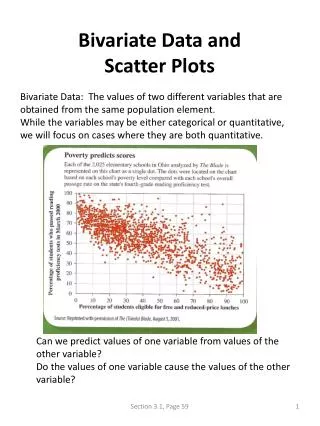
Overview. Currently there is no combined technique for determining the inferred location and depth of a radiological source(s) under shielding objects. Such a method it is believed would have many uses, but it would be of particular use in the decommissioning and land contamination industries. Some of these uses include imaging: Contamination buried within sand and soil, Submerged items, Buried packages,Sealed containers.Such a method would also be of use in the imaging of difficult to9458

E N D
1. Jamie Adams
Engineering Department
Lancaster University Depth determination of buried caesium-137 and cobalt-60 sources using scatter peak data
2. Overview Currently there is no combined technique for determining the inferred location and depth of a radiological source(s) under shielding objects.
Such a method it is believed would have many uses, but it would be of particular use in the decommissioning and land contamination industries.
Some of these uses include imaging:
Contamination buried within sand and soil,
Submerged items,
Buried packages,
Sealed containers.
Such a method would also be of use in the imaging of difficult to access or hazardous environments such as gloveboxes.
3. The Sellafield reprocessing site, UK
4. Introduction An alternative approach to 3D mapping of source location and depth, has been proposed, by combining the insights of two existing techniques.
N-Visage� is a previously established method for obtaining accurate inferred source locations, under a variety of shielding materials and thicknesses. It processes spectral and geometric data given to it and produces an inferred source map.
The relative attenuation method [1] takes the intensity of both a low energy x-ray and a higher energy ?-photopeak from a recorded spectrum and determines some depth discrimination from the relationship encountered.
This relationship has been adapted to use the scatter-peak as x-rays were not distinguishable under the shielding thicknesses used in this research.
5. The N-Visage� technique
Experimental geometries recorded as accurately as possible.
Dimensionally accurate reconstructed model of experimental environment is then created.
Macro used to record the Cartesian coordinates of each spectral recording location in 3D space.
6. Spectral analysis
7. Methods Validation methods for the N-Visage� software conducted at the National Physical Laboratory (Teddington, UK).
Low scatter facility � background radiation levels minimal.
Sources used:
Cobalt-60 (513 MBq)
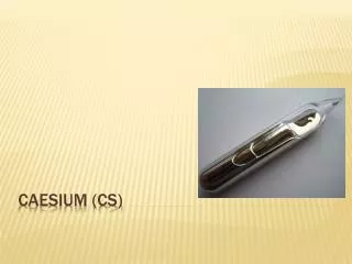
Caesium-137 (24.8 MBq)
Caesium-137 (21.7 MBq)
Pool used to contain water and conduct shielding experiments under: 11, 20 and 30cm of water.
An ICS-4000e Radionuclide Identifier was used in conjunction with an XP Submersible Gamma Ray Probe [2]. The system utilizes a 10mm x 10mm x 1mm cadmium telluride detector, providing energy resolution of 8 keV (1.2% at 662 keV)
8. 800mm2 scanning area
9. Water shielding list
Equipment used for the water shielding experiments
Water shielding experiments
10. The N-Visage� technique Source plane set.
Source and shielding object parameters set including the attenuation coefficient.
Model built and subsequently solved.
Providing an accurate location of all radiological sources present within the environment.
1) A single caesium-137 source placed under 11cm of water
2) A single caesium-137 source placed under 20cm of water
3) Two caesium-137 sources placed under 11cm of water
4) Two caesium-137 sources placed under 20cm of water
5 ) A single cobalt-60 source placed under 11cm of water
6) A single cobalt-60 source placed under 20cm of water
11. Scatter to ?-photopeak relationship
Scatter to ?-photopeak ratios Scatter to ?-photopeak ratio
R= Scatter to ?- photopeak ratio
Sc= Scatter ROI
Pp= ?-photopeak ROI
Inspired by the work conducted by A. Shippen using x-ray to ?-ray ratios
12. Caesium-137 experimental ratios
13. Cobalt-60 experimental ratios
14. Calculating the angle (?) between the vertical source plane and the detector position from the source Calculating the thicknesses of water at a given point Predicting shielding thicknesses MP = 3D locations of the 36 reading points
S = Exact centre of the source object
Cos? = Angle between two the vectors
T = Thickness of water (for that spectral reading point)
D = Known depth of shielding object
This process uses the data recoded in the N-Visage� software, when reconstructing an experimental model.
15. Function fitting Function fitting was carried out to a find relationship linking the scatter and ?-photopeak ROI with the thickness and depth of shielding.
Pr = scatter and ?-photopeak
prediction
D = Depth of water
T = Known thickness of
shielding object
w(n) = Model parameters
Other models were looked
at predicting the depth using
scatter ratio and cos?
parameters.
16. Future work The technique will be combined into N-Visage� so that a 3D model providing the depth as well as the location of radiological sources.
At present while the software is capable of producing 3D source distributions, it is constrained to 2D surface locations due to the amount of data the software has to work with.
Further validation is also planned for the N-Visage� technique, using mixed radionuclide sources, more complex shielding geometries and materials.
The technique has potential for use in storage ponds, sealed containers and buried packages, but the main focus is on its use for land contamination problems.
17. Acknowledgments Dr. Michael Aspinall for use of experimental equipment at NPL (including the scanning rig).
Mr. Alan Shippen for his previous research providing us with the relative attenuation method.
The Engineering and Physical Sciences Research Council (EPSRC),
The North West Development Agency (NWDA),
And REACT Engineering Ltd for sponsoring this research.
The Nuclear Decommissioning Authority (NDA) for funding the validation experiments.
Dr. David Thomas, Mr. Lawrence Jones and staff at the National Physical Laboratory (Teddington, UK).
18. References [1] A. Shippen, and M. J. Joyce, "Profiling the depth of caesium-137 contamination in concrete via a relative linear attenuation model," 7th International Topical Meeting on Industrial Radiation and Radioisotopes, Prague, 2008.
[2] Laurus. Systems, "Advanced Technologies For A Safer World, ICS 4000". [Online]. Available: http://www.LaurusSystems.com.
[3] M.D. Aspinall, "Real time digital assay of mixed radiation fields". PhD Thesis, Lancaster University, 2008.
Sellafield Limited. (2009) . �Image library". [Online]. Available: http://www.sellafieldsites.com/page/media-centre/image-library
Taipei Times. (2009) . "Plan to Import 20,000 Tons of Italian Nuclear Waste into Utah Approved by US Gov". [Online]. Available: http://www.taipeitimes.com.