Download
1 / 6
60 likes | 62 Views
The full form of UML is Unified Modelling Language. Itu2019s a standardized modeling language that consists of multiple diagrams.

E N D
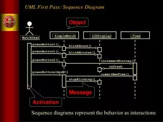
Top Five Types of Diagram Often Used in UML Assignments Most students get UML assignment help online because they get confused with all the diagrams involved in this course. The full form of UML is Unified Modelling Language. It’s a standardised modelling language that consists of multiple diagrams.
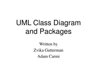
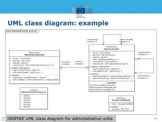
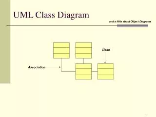
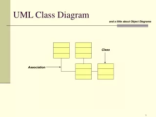
1. Class Diagram This one is a central modelling technique that is applicable to all object-oriented methods. This diagram describes the type of objects in the system and the kind of static relationship that exists between them. The relationships that can exist between objects in this diagram are: · Association · Aggregation · Inheritance You can even talk to UML assignment help providers if you want to know more about these relationships.
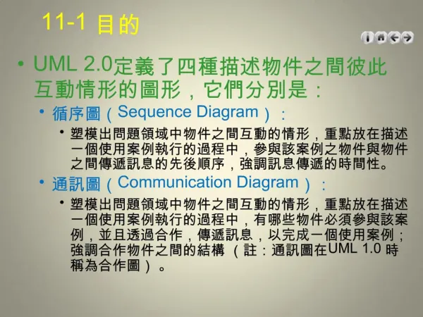
2. Component diagram This diagram shows how different components are wired together to produce software systems or larger components. It shows the architectures of software components and the dependencies between them.
3. Deployment diagram This structure diagram identifies the architecture of the software system. It also shows the distribution of software artefacts to deployment targets. Artefacts are the concrete elements present in our physical world that are also a result of development proves. You may find it hard to understand this diagram initially.
4. Package diagram The package diagram shows packages in a software system and identifies dependencies between the packages. The main purpose of this diagram is to show different aspects of a software system. For example, let’s say you have been asked to build a multi-tiered application this semester. So, you can use the package diagram to view all the layers of your application model.
5. Composite structure diagram The function of a composite structure diagram is very specific. It highlights the internal structure of a class and establishes the relations between different class components. This diagram is ideal if you want to know how a data member of a specific class is related to a data member of another class. In that case, type ‘make my assignment at cheap rates’ on Google and ask for help. Consult with your professors if you still aren’t able to get a solid grip on the diagrams.