Download

1 / 64
670 likes | 1.1k Views
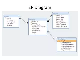
CS 157A Lecture 7. Translation of ER-diagram into Relational Schema. Prof. Sin-Min Lee Department of Computer Science. Learning Objectives. Define each of the following database terms Relation Primary key Foreign key Referential integrity Field Data type Null value.

E N D
CS 157A Lecture 7 Translation of ER-diagram into Relational Schema Prof. Sin-Min Lee Department of Computer Science
Learning Objectives • Define each of the following database terms • Relation • Primary key • Foreign key • Referential integrity • Field • Data type • Null value • Discuss the role of designing databases in the analysis and design of an information system • Learn how to transform an entity-relationship (ER) Diagram into an equivalent set of well-structured relations 9.2
Process of Database Design • Logical Design • Based upon the conceptual data model • Four key steps 1. Develop a logical data model for each known user interface for the application using normalization principles. 2. Combine normalized data requirements from all user interfaces into one consolidated logical database model 3. Translate the conceptual E-R data model for the application into normalized data requirements 4. Compare the consolidated logical database design with the translated E-R model and produce one final logical database model for the application 9.6
Relational Database Model • Data represented as a set of related tables or relations • Relation • A named, two-dimensional table of data. Each relation consists of a set of named columns and an arbitrary number of unnamed rows • Properties • Entries in cells are simple • Entries in columns are from the same set of values • Each row is unique • The sequence of columns can be interchanged without changing the meaning or use of the relation • The rows may be interchanged or stored in any sequence 9.8
Relational Database Model • Well-Structured Relation • A relation that contains a minimum amount of redundancy and allows users to insert, modify and delete the rows without errors or inconsistencies 9.9
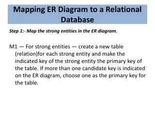
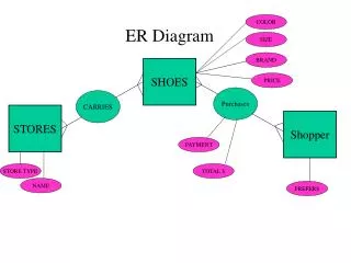
Transforming E-R Diagrams into Relations • It is useful to transform the conceptual data model into a set of normalized relations • Steps • Represent entities • Represent relationships • Normalize the relations • Merge the relations 9.10
Transforming E-R Diagrams into Relations • The primary key must satisfy the following two conditions • The value of the key must uniquely identify every row in the relation • The key should be nonredundant 9.11
Transforming E-R Diagrams into Relations • Represent Relationships • Binary 1:N Relationships • Add the primary key attribute (or attributes) of the entity on the one side of the relationship as a foreign key in the relation on the right side • The one side migrates to the many side 9.14
Transforming E-R Diagrams into Relations • Binary or Unary 1:1 • Three possible options • Add the primary key of A as a foreign key of B • Add the primary key of B as a foreign key of A • Both 9.16
Transforming E-R Diagrams into Relations • Represent Relationships (continued) • Binary and higher M:N relationships • Create another relation and include primary keys of all relations as primary key of new relation 9.17
Transforming E-R Diagrams into Relations • Unary 1:N Relationships • Relationship between instances of a single entity type • Utilize a recursive foreign key • A foreign key in a relation that references the primary key values of that same relation • Unary M:N Relationships • Create a separate relation • Primary key of new relation is a composite of two attributes that both take their values from the same primary key 9.19
Primary Key Constraints • A set of fields is a keyfor a relation if : 1. No two distinct tuples can have same values in all key fields, and 2. This is not true for any subset of the key. • Part 2 false? A superkey. • If there’s >1 key for a relation, one of the keys is chosen (by DBA) to be the primary key. • E.g., sid is a key for Students. (What about name?) The set {sid, gpa} is a superkey. Primary key can not have null value
Foreign Keys, Referential Integrity • Foreign key : Set of fields in one relation that is used to `refer’ to a tuple in another relation. (Must correspond to primary key of the second relation.) Like a `logical pointer’. • E.g. sid is a foreign key referring to Students: • Enrolled(sid: string, cid: string, grade: string) • If all foreign key constraints are enforced, referential integrity is achieved, i.e., no dangling references. • Can you name a data model w/o referential integrity? • Links in HTML!
Enforcing Referential Integrity • Consider Students and Enrolled; sid in Enrolled is a foreign key that references Students. • What should be done if an Enrolled tuple with a non-existent student id is inserted? (Reject it!) • What should be done if a Students tuple is deleted? • Also delete all Enrolled tuples that refer to it. • Disallow deletion of a Students tuple that is referred to. • Set sid in Enrolled tuples that refer to it to a default sid. • (In SQL, also: Set sid in Enrolled tuples that refer to it to a special value null, denoting `unknown’ or `inapplicable’.) • Similar if primary key of Students tuple is updated.
name ssn lot Employees Logical DB Design: ER to Relational • Entity sets to tables. CREATE TABLE Employees (ssn CHAR(11), name CHAR(20), lot INTEGER, PRIMARY KEY (ssn))
Relationship Sets to Tables CREATE TABLE Works_In( ssn CHAR(1), did INTEGER, since DATE, PRIMARY KEY (ssn, did), FOREIGN KEY (ssn) REFERENCES Employees, FOREIGN KEY (did) REFERENCES Departments) • In translating a relationship set to a relation, attributes of the relation must include: • Keys for each participating entity set (as foreign keys). • This set of attributes forms a superkey for the relation. • All descriptive attributes.
since name dname ssn lot Employees Manages Review: Key Constraints • Each dept has at most one manager, according to the key constrainton Manages. budget did Departments Translation to relational model? 1-to-1 1-to Many Many-to-1 Many-to-Many
Translating ER Diagrams with Key Constraints CREATE TABLE Manages( ssn CHAR(11), did INTEGER, since DATE, PRIMARY KEY (did), FOREIGN KEY (ssn) REFERENCES Employees, FOREIGN KEY (did) REFERENCES Departments) • Map relationship to a table: • Note that did is the key now! • Separate tables for Employees and Departments. • Since each department has a unique manager, we could insteadcombine Manages and Departments. CREATE TABLE Dept_Mgr( did INTEGER, dname CHAR(20), budget REAL, ssn CHAR(11), since DATE, PRIMARY KEY (did), FOREIGN KEY (ssn) REFERENCES Employees)
Review: Participation Constraints • Does every department have a manager? • If so, this is a participation constraint: the participation of Departments in Manages is said to be total (vs. partial). • Every did value in Departments table must appear in a row of the Manages table (with a non-null ssn value!) since since name name dname dname ssn did did budget budget lot Departments Employees Manages Works_In since
Participation Constraints in SQL • We can capture participation constraints involving one entity set in a binary relationship, but little else (without resorting to CHECK constraints). CREATE TABLE Dept_Mgr( did INTEGER, dname CHAR(20), budget REAL, ssn CHAR(11) NOT NULL, since DATE, PRIMARY KEY (did), FOREIGN KEY (ssn) REFERENCES Employees, ON DELETE NO ACTION)
Review: Weak Entities • A weak entity can be identified uniquely only by considering the primary key of another (owner) entity. • Owner entity set and weak entity set must participate in a one-to-many relationship set (1 owner, many weak entities). • Weak entity set must have total participation in this identifying relationship set. name cost pname age ssn lot Policy Dependents Employees
Translating Weak Entity Sets • Weak entity set and identifying relationship set are translated into a single table. • When the owner entity is deleted, all owned weak entities must also be deleted. CREATE TABLE Dep_Policy ( pname CHAR(20), age INTEGER, cost REAL, ssn CHAR(11) NOT NULL, PRIMARY KEY (pname, ssn), FOREIGN KEY (ssn) REFERENCES Employees, ON DELETE CASCADE)
name ssn lot Employees Policies policyid cost name ssn lot Employees Beneficiary Policies policyid cost Review: Binary vs. Ternary Relationships pname • If each policy is owned by just 1 employee: • Key constraint on Policies would mean policy can only cover 1 dependent! • What are theadditional constraints in the 2nd diagram? age Dependents Covers Bad design pname age Dependents Purchaser Better design
Binary vs. Ternary Relationships (Contd.) CREATE TABLE Policies ( policyid INTEGER, cost REAL, ssn CHAR(11) NOT NULL, PRIMARY KEY (policyid). FOREIGN KEY (ssn) REFERENCES Employees, ON DELETE CASCADE) • The key constraints allow us to combine Purchaser with Policies and Beneficiary with Dependents. • Participation constraints lead to NOT NULL constraints. • What if Policies is a weak entity set? CREATE TABLE Dependents( pname CHAR(20), age INTEGER, policyid INTEGER, PRIMARY KEY (pname, policyid). FOREIGN KEY (policyid) REFERENCES Policies, ON DELETE CASCADE)
An Example CREATE TABLE Student ( ID NUMBER, Fname VARCHAR2(20), Lname VARCHAR2(20), );
Constraints in Create Table • Adding constraints to a table enables the database system to enforce data integrity. • Different types of constraints: * Not Null * Default Values * Unique * Primary Key * Foreign Key * Check Condition
Not Null Constraint CREATE TABLE Student ( ID NUMBER, Fname VARCHAR2(20) NOT NULL, Lname VARCHAR2(20) NOT NULL, );
Primary Key Constraint CREATE TABLE Student ( ID NUMBER PRIMARY KEY, Fname VARCHAR2(20) NOT NULL, Lname VARCHAR2(20) NOT NULL, ); Primary Key implies: * NOT NULL * UNIQUE. There can only be one primary key.
Primary Key Constraint (Syntax 2) CREATE TABLE Students ( ID NUMBER, Fname VARCHAR2(20) NOT NULL, Lname VARCHAR2(20) NOT NULL, PRIMARY KEY(ID) ); Needed when the primary key is made up of two or more fields
What additional constraint do we want on Student? What should be the primary key? Another Table CREATE TABLE Studies( Course NUMBER, Student NUMBER );
Foreign Key Constraint CREATE TABLE Studies( Course NUMBER, Student NUMBER, FOREIGN KEY (Student) REFERENCES Students(ID) ); NOTE: ID must be unique (or primary key) in Student
Relations vs. Tables • We show how to translate ER-Diagrams to table definitions • Sometimes, people translate ER-Diagrams to relation definitions, which is more abstract than table definitions. • e.g., Student(ID, Fname, Lname); • table definitions contain, in addition, constraints and datatypes
Translating Entities birthday id General Rule: • Create a table with the name of the Entity. • There is a column for each attribute • The key in the diagram is the primary key of the table Actor name address
Translating Entities birthday id create table Actor(id varchar2(20) primary key, name varchar2(40), birthday date, address varchar2(100)); Actor name address Relation: Actor (id, name, birthday, address)
Translating Relationships (without constraints) title birthday General Rule: • Create a table with the name of the relationship • The table has columns for all of the relationship's attributes and for the keys of each entity participating in the relationship • What is the primary key of the table? • What foreign keys are needed? id Film Actor year Acted In name salary type address
Translating relationships (without constraints) title birthday What would be the relation for ActedIn? How would you define the table for ActedIn? id Film Actor year Acted In name salary type address